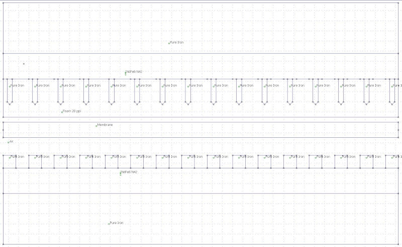
Back to the usual, ideal solid pole pieces, view:
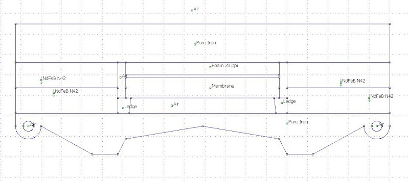
I've put in a ledge to which the membrane now easily can be attached to.
The ledge has an angle to get a initial throat exansion.
Also, the foam actually continues upwards, that is backwards in reality, between the back pole pieces.
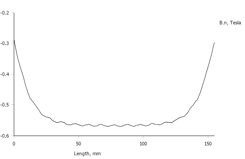
Simulation:

Flow density at the rim:
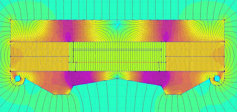

and in the middle:

Looking really good!
Well, back to the shop to cut 32 pieces of 15x2 mm iron rods 145 mm long and sand them in the middle where the edge meets the membrane.
And get some ledges mounted...
I've put in a ledge to which the membrane now easily can be attached to.
The ledge has an angle to get a initial throat exansion.
Also, the foam actually continues upwards, that is backwards in reality, between the back pole pieces.
Simulation:
Flow density at the rim:
and in the middle:
Looking really good!
Well, back to the shop to cut 32 pieces of 15x2 mm iron rods 145 mm long and sand them in the middle where the edge meets the membrane.
And get some ledges mounted...

Thought for a while to also have the front pole pieces backs being slanted, but the first front wave reflection should go straight back; not being deflected and thus mixed with with the adjacent first front waves:
Altough the simulations did show a 5 % increase in the magnetic flux density:

it is no longer linear across the membranes area:
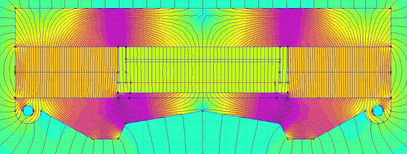
So that suggestion just got documented and forgotten...
Added some material tags (foam, membrane) for the different areas in the inverted motor as well just for clarification. The simulation doesn't change.
Altough the simulations did show a 5 % increase in the magnetic flux density:
it is no longer linear across the membranes area:
So that suggestion just got documented and forgotten...
Added some material tags (foam, membrane) for the different areas in the inverted motor as well just for clarification. The simulation doesn't change.
Coud you double the amount of 2mm steel bars to get more linariety.
Bernt
Yes, of course.
But then the reduction of the reflection of the back wave will be less.
Also, there´s still variations for the part of the membrane at the front pole pieces.
FEMM:

Flux density at back pole pieces:


Flux density at front pole pieces:

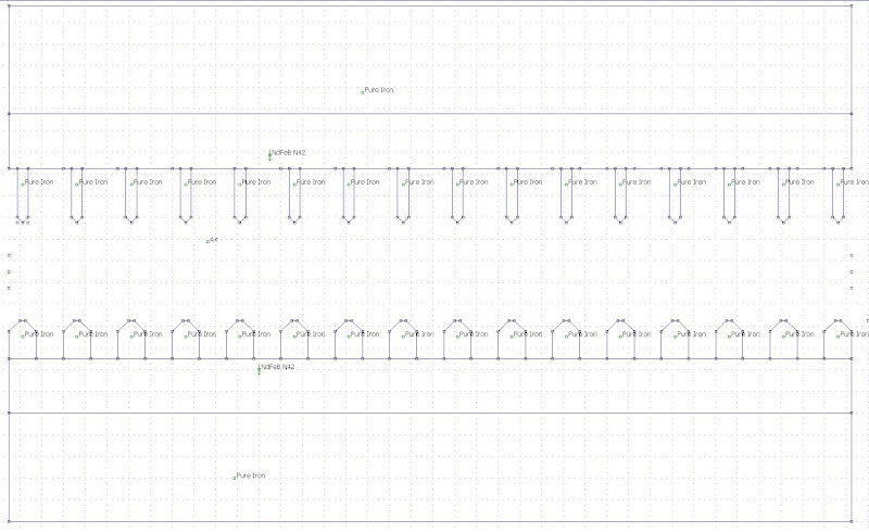
Anyway, since the motor now is "open" at the back and the back pole pieces are only held in place by the magnets, everything is up for grabs when it comes to back pole pieces configuration.
I had a crazy idea: what if you made the pole pieces out of open cell iron foam? Something like this:
Wouldn't that reduce reflections and make the magnetic field more even?
/Anton
An externally hosted image should be here but it was not working when we last tested it.
Wouldn't that reduce reflections and make the magnetic field more even?
/Anton
During simulation and design, you could neglect the 2nd harmonic and focus mor on the odd ones. The ear itself generates up to 10% 2nd harmonic so you cant really hear difference between 1% or 2% 2nd harmonic distortion.
So if it helps you with the design of magnet motor, focus less on the second and more on the third.
When it comes to the sharpening of the pole piece try something "lagom" and not so extremely sharp.
https://lh3.googleusercontent.com/-...AKE/IttcvYjGXkk/s462-Ic42/polstyckeprofil.jpg
So if it helps you with the design of magnet motor, focus less on the second and more on the third.
When it comes to the sharpening of the pole piece try something "lagom" and not so extremely sharp.
https://lh3.googleusercontent.com/-...AKE/IttcvYjGXkk/s462-Ic42/polstyckeprofil.jpg
Yes, of course.During simulation and design, you could neglect the 2nd harmonic and focus mor on the odd ones. The ear itself generates up to 10% 2nd harmonic so you cant really hear difference between 1% or 2% 2nd harmonic distortion.
So if it helps you with the design of magnet motor, focus less on the second and more on the third.
If the bottom is towards the membrane, that bevel is feasible and will probably be what I'll do. It will be much harder to accomplish slant at the top.When it comes to the sharpening of the pole piece try something "lagom" and not so extremely sharp.

http://projekter.aau.dk/projekter/files/9852082/07gr1061_Thesis.pdf
Look on page 18...
Several studies has shown that 2nd harmonic is not critical.
I can give an example tried myself.
Using Dipole bass with double transducers on each channel, the first clever thought would be to mount them at opposite directions to cancel distortion right? Well it´s "only" the secon harmonic that is cancelled, higher orders is uneffected. The percieved sound is way better if both transducers is working in same direction. The 2nd harmonic seems to have a masking effect on those with higher order.
I live more "värst" than you in "värsta Götaland" btw
Yes, of course. You are preaching to the choirhttp://projekter.aau.dk/projekter/files/9852082/07gr1061_Thesis.pdf
Look on page 18...
Several studies has shown that 2nd harmonic is not critical.
 .
.Been there myself:I can give an example tried myself.
Using Dipole bass with double transducers on each channel, the first clever thought would be to mount them at opposite directions to cancel distortion right? Well it´s "only" the secon harmonic that is cancelled, higher orders is uneffected. The percieved sound is way better if both transducers is working in same direction. The 2nd harmonic seems to have a masking effect on those with higher order.
If you have almost the same nick at a Swedish forum, I think that we had a chat some years ago at a DIY meeting in Göteborg.I live more "värst" than you in "värsta Götaland" btw
In fact, I think that you (and Bernt) convinced me to abandon the setup above.
Any comment on my last post:
"If the bottom is towards the membrane, that bevel is feasible and will probably be what I'll do. It will be much harder to accomplish slant at the top."
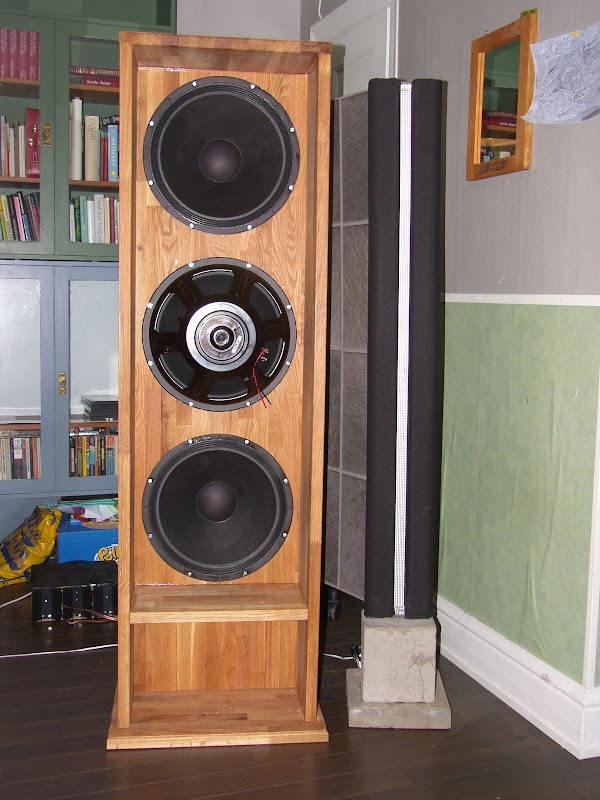
Reality
So I made some measurements with the thinner back pole pieces and the new motor, Mk II B:

Squeezed the HVAC foam in between them:

Now the AMT is fixed in the larger baffle, but I still need to get a waveguide.
Did a Q&D first:

Did an SPL measurement at 1 W/ 1 m, still a couple of dBs above 100 dBA.
So far so good...
So I made some measurements with the thinner back pole pieces and the new motor, Mk II B:
Squeezed the HVAC foam in between them:
Now the AMT is fixed in the larger baffle, but I still need to get a waveguide.
Did a Q&D first:
Did an SPL measurement at 1 W/ 1 m, still a couple of dBs above 100 dBA.
So far so good...
Measurements
I wasn't pleased with the frequency response at 1 m, so I thought that I make near-field measurements instead; at 20 cm.
Still not happy with the frequency response though, way too much variation in level.
Although I suspect that the Q&D waveguide has something to do with the level variations in the lower end.
Funny thing is that with foam or without foam, the response look more or less the same (green is with foam):
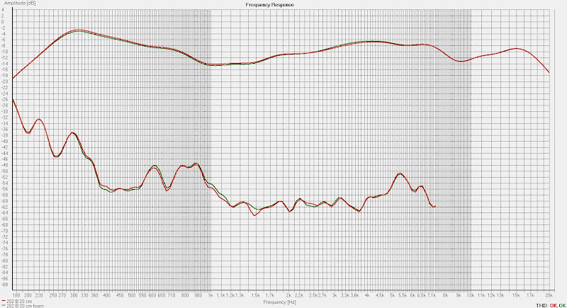
2nd and 3rd harmonic distortions:
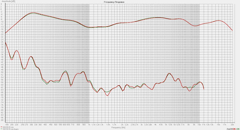

I'd say that those 3rd HD distortion levels are pretty low, or what do you say esl 63?
All the above are shown with 1/3 octave smoothing.
But at 1/24 octave smoothing (red curve) it looks more or less the same:
Next step will be to get rid of the foam and thus get the membrane exactly in the middle of the gap.
And perhaps test an even sharper bevel on the back pole pieces.
And of course get a S&C waveguide. (Slow and Clean??)
I wasn't pleased with the frequency response at 1 m, so I thought that I make near-field measurements instead; at 20 cm.
Still not happy with the frequency response though, way too much variation in level.
Although I suspect that the Q&D waveguide has something to do with the level variations in the lower end.
Funny thing is that with foam or without foam, the response look more or less the same (green is with foam):
2nd and 3rd harmonic distortions:
I'd say that those 3rd HD distortion levels are pretty low, or what do you say esl 63?
All the above are shown with 1/3 octave smoothing.
But at 1/24 octave smoothing (red curve) it looks more or less the same:
Next step will be to get rid of the foam and thus get the membrane exactly in the middle of the gap.
And perhaps test an even sharper bevel on the back pole pieces.
And of course get a S&C waveguide. (Slow and Clean??)
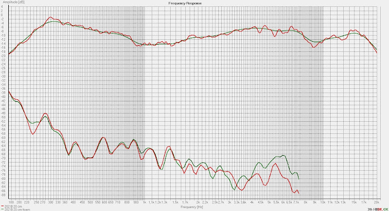
Made the back pole pieces a little sharper but also changed the membrane design; now the two contact stripes are at the same side. Positioned the membrane in the middle of the gap.
Also made a slightly better wave guide and had the HVAC foam between the back pole pieces.
Measured at 50 cm (green) and 1 m (red), 1/12 octave smoothing,
2nd HD:

3rd HD:

So if a properly designed wave guide will make the low end response a little more even (distortion is from the room in the LF BTW) there's only one PEQ at 4800 Hz -6 dB to do.
I mean, the distortion levels are so low now, especially the 3 rd HD, that any try to mitigate a peak most likely will result in that other peaks will emerge.
Of course, I'll be more than glad to be proven wrong.
Also made a slightly better wave guide and had the HVAC foam between the back pole pieces.
Measured at 50 cm (green) and 1 m (red), 1/12 octave smoothing,
2nd HD:
3rd HD:
So if a properly designed wave guide will make the low end response a little more even (distortion is from the room in the LF BTW) there's only one PEQ at 4800 Hz -6 dB to do.
I mean, the distortion levels are so low now, especially the 3 rd HD, that any try to mitigate a peak most likely will result in that other peaks will emerge.
Of course, I'll be more than glad to be proven wrong.
Last edited:


Little change in the frequency response and even higher distortion levels with the pieces of plastics (red):


So I'd say that I'm better off without them. Not sure about the foam between the back pole pieces though (green with foam and blue without foam), but it will be fairly easy to continue experiment with different thickness and so on later.
For sure, I must have some dampening between the back of the AMT and the pole the woofers are mounted in.
- Status
- This old topic is closed. If you want to reopen this topic, contact a moderator using the "Report Post" button.
- Home
- Loudspeakers
- Planars & Exotics
- Yet another DIY AMT