Another simulated view
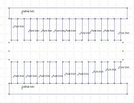
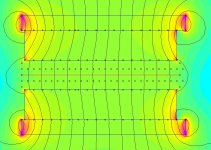
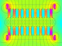
So I got the idea to invert the motor and simulate it from the side.
I hope that you get the picture, it is barely half a motor wide.
I believe that the field in the gap is really can be simulated this way.
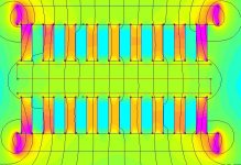
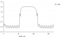
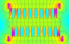
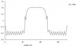
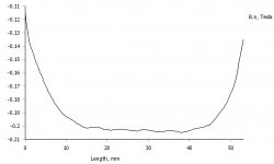
In the simulated middle view you see the contour at the lower, middle and higher part of the gap. The plot shows the field along that contour. It is only in the middle of the gap the field is even.
So I got the idea to invert the motor and simulate it from the side.
I hope that you get the picture, it is barely half a motor wide.
I believe that the field in the gap is really can be simulated this way.
In the simulated middle view you see the contour at the lower, middle and higher part of the gap. The plot shows the field along that contour. It is only in the middle of the gap the field is even.
Attachments

Is this "motor " the same as you started with?
If so,I think your drawing is wrong.
The iron must bee on the same magnet.Your draving shows 2 magnets.
I might be wrong,but i dont think you shuld worry about the magnetic field,to me it looks fine from the first simulations.
Bernt
If so,I think your drawing is wrong.
The iron must bee on the same magnet.Your draving shows 2 magnets.
I might be wrong,but i dont think you shuld worry about the magnetic field,to me it looks fine from the first simulations.
Bernt
Rounded edges
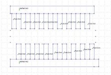
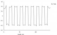
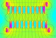
So what if the edges of the iron rods in the gap were rounded?
First two is with square corners, the last two with rounded corners.
The field is stronger, but also has higher fluctuations.
So what if the edges of the iron rods in the gap were rounded?
First two is with square corners, the last two with rounded corners.
The field is stronger, but also has higher fluctuations.
Attachments
I think you have to use a 3D simulating program to get it right.
Bernt
Yes, but this is just a comparative study.
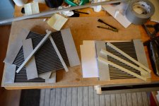
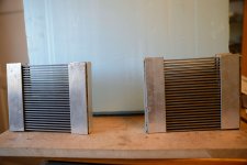
Assembling the motor, pt 2.
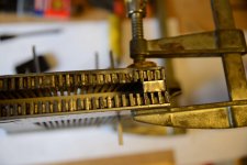
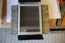
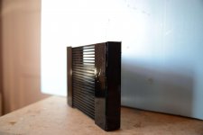
First I made dummies for the gap, to keep the space open and stopping the magnets from intruding it.
Then mounted the dummies and loaded the first set of magnets.
I will probably load one complete side as the next step. I only got two clamps long enough, so it will have to be it two sessions.
First I made dummies for the gap, to keep the space open and stopping the magnets from intruding it.
Then mounted the dummies and loaded the first set of magnets.
I will probably load one complete side as the next step. I only got two clamps long enough, so it will have to be it two sessions.
Attachments

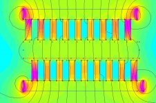
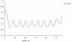
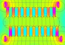
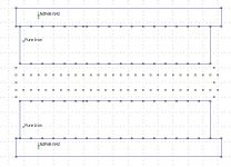
Simulated rods vs solid
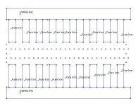
In the inverted motor I was able to study what happened with the field with respect to offset or rounded edges of the rods.
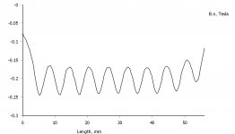
What if the iron was solid instead of 3 mm rods with 3 mm space inbetween?
The first three below is the rod simulation and the second three is with solid iron. Note that the layout is just for simulating the field, it is not the real motor.
So the field is actually higher with rods, even if it is not so linear.
In the inverted motor I was able to study what happened with the field with respect to offset or rounded edges of the rods.
What if the iron was solid instead of 3 mm rods with 3 mm space inbetween?
The first three below is the rod simulation and the second three is with solid iron. Note that the layout is just for simulating the field, it is not the real motor.
So the field is actually higher with rods, even if it is not so linear.
Attachments

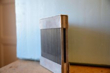
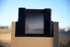
Assembling the motor, pt 3.
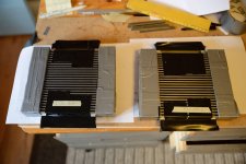
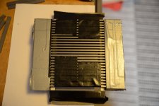
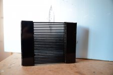
So I mounted some more magnets, painted the motors black in order to hide some of the imperfections. Then I made some baffles.
Now I´m waiting for the 3M tape to arrive.
So I mounted some more magnets, painted the motors black in order to hide some of the imperfections. Then I made some baffles.
Now I´m waiting for the 3M tape to arrive.
Attachments
-
 2013_04_01-555.jpg847.6 KB · Views: 748
 -
 2013_04_01-553.jpg400.2 KB · Views: 613
 -
 2013_04_01-552.jpg519.2 KB · Views: 573
 -
 2013_04_01-548.jpg486.5 KB · Views: 561
 -
 2013_04_01-547.jpg655.6 KB · Views: 638
 -
 2013_04_01-544.jpg374.8 KB · Views: 638
 -
 2013_03_30-517.jpg527.1 KB · Views: 517
 -
 2013_04_01-561.jpg636.8 KB · Views: 799
To be honest, I don´t know. Yet.
It´ll be a lot of experimenting and I must first learn how this motor behaves.
The only thing I really know is that I will be using your excellent technique with the Alu on paper foil together with the 3M 74 Tape.
So folks, I have been waiting a long time to be able to say this:
Pleats, don´t fail me now!
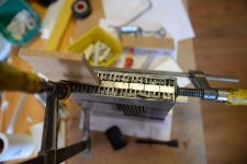
First membrane
I thought of having a simple layout at first.
The gap is 120 mm wide so why not have a 7,5 + 2,5 mm layout with 5 mm Alu strips.
The pleats are 7,5 mm deep and 2,5 mm apart.
That´ll be 120/2,5 = 48 pleats.
Unfolded the membrane is 48 x (7,5 + 2,5) = 480 mm.
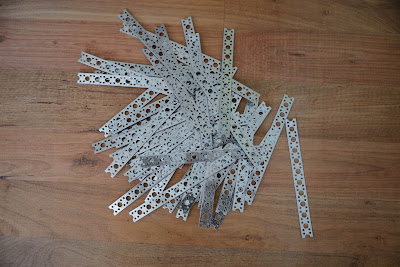
So I cut a nail strip into 200 mm long strips to build a pleating tool:
I thought of having a simple layout at first.
The gap is 120 mm wide so why not have a 7,5 + 2,5 mm layout with 5 mm Alu strips.
The pleats are 7,5 mm deep and 2,5 mm apart.
That´ll be 120/2,5 = 48 pleats.
Unfolded the membrane is 48 x (7,5 + 2,5) = 480 mm.
So I cut a nail strip into 200 mm long strips to build a pleating tool:
Last edited:
I have been calculating a bit.
I use 30 pleats in my latest model,and with 5,5mm stripes i get 3,8 ohm.
I recomend you to use 7,5mm stripes for low impedance and to cover more surface with alufoil.
I have another tool in my mind to get paralel pleats.
Your nailstrip is only 1mm.It might be better with 2,5mm.
Keep up the good work.
Bernt
- Status
- This old topic is closed. If you want to reopen this topic, contact a moderator using the "Report Post" button.
- Home
- Loudspeakers
- Planars & Exotics
- Yet another DIY AMT