Of course there is - if you look at the schematic directly above your post, to get a balanced output you'd take the two complementary phases from pins 7 and 10. Pins 6 & 9 would go to GND.
Thanks abraxalito, that's perfect answer.
Actually option1 has no DC current passing through while all the other options have balanced DC offset current (DC current of option4 might be very small). The working conditions are totally different. What's your point at different options?
Regards,
Ian
Thanks Ian, Abrax
Another theoretical question to improve my understanding. Could you comment on the pro/cons between an active IV stage and one using an xformer.
What output signal level is achievable with a transformer.
thanks
Another theoretical question to improve my understanding. Could you comment on the pro/cons between an active IV stage and one using an xformer.
What output signal level is achievable with a transformer.
thanks
As far as I can see, strictly speaking the transformer's not doing I/V here - its doing output isolation and gain matching/balancing. To be an I/V stage it'd need to present a very low impedance to the DAC chip.
That said, an active I/V stage could be used together with a transformer. For an example of an active I/V look no further than the NTD1 project - opc's NTD1 project
That said, an active I/V stage could be used together with a transformer. For an example of an active I/V look no further than the NTD1 project - opc's NTD1 project
As far as I can see, strictly speaking the transformer's not doing I/V here - its doing output isolation and gain matching/balancing. To be an I/V stage it'd need to present a very low impedance to the DAC chip.
That said, an active I/V stage could be used together with a transformer. For an example of an active I/V look no further than the NTD1 project - opc's NTD1 project
Thanks Abraxalito,
Yes, it's true. ESS DACs are not in pure current output mode. The output stage is a voltage source in serial with internal resistance. It can only be considered as current output when load impudence is closed to zero.
How about using a pair of OPA861 to convert ESS outputs into balanced current source, than into a transformer?
Thanks for the link . Actually I bought a NTD1 KIT years ago. But I have been too busy to build it. Maybe it's the time to give a try.
Regards,
Ian
Last edited:
OPA861 would certainly do the job and its got a good reputation for I/V duty as far as I'm aware. I'd be a bit concerned though about its 3rd harmonic distortion figure, given that one of the things attracting customers is ESS's very low THD+N numbers, these might be thrown out the window by attaching an OPA861. The DS only shows 2nd/3rd harmonic at 5MHz so its anyone's guess how much better it'll be at audio freqs.
Also is OPA861's 10ohm input impedance low enough to be considered 'current mode' from the point of view of the DAC chip?
My own reservations with the NTD1 are that its such a power hog - I've an I/V stage where I'm running much lower quiescent currents and much lower supplies but its operation is very similar to NTD1's. There are more recently released MOSFETs which look to provide very high gm at quite reasonable output currents. SSM3K339R is one such but being sot23 it cannot dissipate much power.
You can use Lundahl LL1684 direct on ES output, like this
http://www.audiodesignguide.com/DAC32/Suppler-V-I-LL1684-for-DAC.jpg
http://www.audiodesignguide.com/DAC32/Suppler-V-I-LL1684-for-DAC.jpg
IMHO people are biased against transformers because it’s too simple.
Judging by my current setup with a ESS9018 and Lundahl transformers, I can crank it up to nosebleed levels with ease and I have it hooked up in 2:1 mode. Most people probably don’t need more than the output delivered from the chip. It isolates the circuit and balances it. If you need it you can multiply the voltage upwards.
Silicon might be able to artificially create beneficial load conditions but you’re comparing a piece of wire with a silicon network. I put my trust in the piece of wire...
I’m not saying that it’s the end all be all, but it shouldn’t be overlooked just because it’s a super simple passive solution.
IMHO people are biased against transformers because it’s too simple.
Judging by my current setup with a ESS9018 and Lundahl transformers, I can crank it up to nosebleed levels with ease and I have it hooked up in 2:1 mode. Most people probably don’t need more than the output delivered from the chip. It isolates the circuit and balances it. If you need it you can multiply the voltage upwards.
Silicon might be able to artificially create beneficial load conditions but you’re comparing a piece of wire with a silicon network. I put my trust in the piece of wire...
I’m not saying that it’s the end all be all, but it shouldn’t be overlooked just because it’s a super simple passive solution.
Hi markusA,
My ES9018K2M/9028Q2M/9038Q2M will have RAW balanced output. So they will open to all different kinds of I/V stage as daughter board or at external.
I did a transformer I/V for my TDA1541A DAC when I was working on my tube pre amp project many years ago. It was very impressed.
Magnetic gears have magic to sound quality. Rail to Rail, MM/MC, tube amplifier with input/output transformer, they all sound fabulous, that's the reason.
I'll try transformer I/V stage for this project for sure. I'll post update once I have. Please also let me know if there is any suggestion or recommendation.
Regards,
Ian
Last edited:
Design DSD/I2S DAC HATs for Raspberry Pi, start from ES9018K2M
It’s all quite an enigma. Op amps measure great, but for some reason they seem to lack some magic ingredient? Going by measurements alone, they would be hard to beat, but once you stop comparing technical data, your ears often tell a very different tale. It’s both frustrating and what makes hifi so special, all at once.
I have a very interesting tube circuit somewhere on the hdd but it would be sweet with a good discrete solution as well. Either way, I think buffer and fully balanced outputs is a good goal. Gain isn’t really needed unless you have a very low amplifying amp.
My tube circuit was fully balanced with a Russian version of the ecc88, that’s the name of the tube, right? Not schoolbook balanced but sort of a sneaky dirty way, lol.
Last edited:
It’s all quite an enigma. Op amps measure great, but for some reason they seem to lack some magic ingredient? Going by measurements alone, they would be hard to beat, but once you stop comparing technical data, your ears often tell a very different tale. It’s both frustrating and what makes hifi so special, all at once.
Agreed - I have a hunch that its in part to do with RF, opamps don't like it and DACs are full of it. Its why nowadays I put a passive filter right after my DAC chips, so the the RF doesn't get to interfere with the active circuits. When there's RF present, passive is the way to go. Which is one reason transformers sound so good - they also provide some filtering to the downstream stages in addition to common-mode noise reduction.
OPA861 would certainly do the job and its got a good reputation for I/V duty as far as I'm aware. I'd be a bit concerned though about its 3rd harmonic distortion figure, given that one of the things attracting customers is ESS's very low THD+N numbers, these might be thrown out the window by attaching an OPA861. The DS only shows 2nd/3rd harmonic at 5MHz so its anyone's guess how much better it'll be at audio freqs.
Also is OPA861's 10ohm input impedance low enough to be considered 'current mode' from the point of view of the DAC chip?
My own reservations with the NTD1 are that its such a power hog - I've an I/V stage where I'm running much lower quiescent currents and much lower supplies but its operation is very similar to NTD1's. There are more recently released MOSFETs which look to provide very high gm at quite reasonable output currents. SSM3K339R is one such but being sot23 it cannot dissipate much power.
Hi Abraxalito,
I don't want to make a oven. So, I'm more interested in your approach. Do you have more information about your IV "with much lower quiescent currents and much lower supplies" ?
There are thousands of different kinds of MOSFETs, but most of them are targeted switching mode, even the one you mentioned SSM3K339R.
My question is that, according to what specification you chose MOSFETs for this kind of audio applications? High gm? Linearity of Vgs-Id curve? Or, something else?
Regards,
Ian
Hi Ian
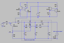
I've attached a schematic showing the output stage I'm using in my latest DAC design. This illustrates the idea - the I/V transistor (BC807-40) needs to run at a substantial bias to present a low enough impedance to the passive filter (around 2ohm or so in this case). It could just as easily be a MOSFET as a bipolar, I'm using a BC807 for cheapness. However no MOSFET has as high a gm as a bipolar, the K339R comes about the closest I've seen, about half as much transconductance. It therefore needs higher bias currents from the CCSs.
The reason this circuit doesn't dissipate as much power as the NTD1 does is that the whole of the bias current isn't run through the I/V resistor. If it were, the supply voltages would have to be much higher. Instead the current is 'bled off' via a current source across the resistor.
As for the choice of MOSFET - its about gm primarily, coupled with not having too high capacitances. MOSFET capacitances are quite non-linear so will contribute harmonic distortion which rises with frequency.
Attachments
Hi Ian
I've attached a schematic showing the output stage I'm using in my latest DAC design. This illustrates the idea - the I/V transistor (BC807-40) needs to run at a substantial bias to present a low enough impedance to the passive filter (around 2ohm or so in this case). It could just as easily be a MOSFET as a bipolar, I'm using a BC807 for cheapness. However no MOSFET has as high a gm as a bipolar, the K339R comes about the closest I've seen, about half as much transconductance. It therefore needs higher bias currents from the CCSs.
The reason this circuit doesn't dissipate as much power as the NTD1 does is that the whole of the bias current isn't run through the I/V resistor. If it were, the supply voltages would have to be much higher. Instead the current is 'bled off' via a current source across the resistor.
As for the choice of MOSFET - its about gm primarily, coupled with not having too high capacitances. MOSFET capacitances are quite non-linear so will contribute harmonic distortion which rises with frequency.
Thanks Abraxalito for the schematic, it's a very smart design. Looks fantastic.
Does it use single supply? Do you have simulation result? Thant will be much help for me to understand the principle.
Thanks again.
Ian
Thanks Abraxalito for the schematic, it's a very smart design. Looks fantastic.
Thank you!
Does it use single supply? Do you have simulation result? Thant will be much help for me to understand the principle.
Yes it does use a single supply though that entails using output capacitors as the output has a half-rail offset. Or with a negative rail generator (say ICL7660 or similar) the offset can be taken down to a much lower level.
Simulations I've done for the frequency response and I've built a few and measured frequency response and THD for a sinewave input. THD performance isn't stellar as you'd expect for such a simple circuit. It reaches around 0.2% THD (2nd and 3rd harmonics predominantly) at high frequencies (5kHz say). There are ways to improve on this - a cascode arrangement will help.
Design DSD/I2S DAC HATs for Raspberry Pi, start from ES9018K2M
If we’re exploring different options, it would be really cool with a tube buffer. My wishlist would contain 1. Balanced topology to match my amps + I like xlr connectors. 2. Using 6n23p (6dj8) tubes since I have a box full of them.
Having said that, I have some annoying questions I can’t shake. Can you make it better than transformers? Or if transformers are used in the circuit, do you really need the tubes? And just because I’m curious, could you make something interesting with tubes and Autoformers for volume controls?
And why would one even bother since the digital volume control is already built in? This is the kind of stuff that keep me awake at night, lol.
For some perverse reason, I keep coming back to circlotrons?
P.S Sonic pros & cons aside, who doesn’t love the glow from tubes when you turn the light down while listening to some favorite piece of music. [emoji6]
Last edited:
It’s all quite an enigma. Op amps measure great, but for some reason they seem to lack some magic ingredient? Going by measurements alone, they would be hard to beat, but once you stop comparing technical data, your ears often tell a very different tale. It’s both frustrating and what makes hifi so special, all at once.
I have a very interesting tube circuit somewhere on the hdd but it would be sweet with a good discrete solution as well. Either way, I think buffer and fully balanced outputs is a good goal. Gain isn’t really needed unless you have a very low amplifying amp.
My tube circuit was fully balanced with a Russian version of the ecc88, that’s the name of the tube, right? Not schoolbook balanced but sort of a sneaky dirty way, lol.
A box of ECC88?🙂 What brand?
Ian
Oh, I wouldn’t know. It’s the Russian 6n23p tube, a 6dj8 equivalent I believe.
It could quite possibly be a grab bag of different brands?
It could quite possibly be a grab bag of different brands?
Oh, I wouldn’t know. It’s the Russian 6n23p tube, a 6dj8 equivalent I believe.
It could quite possibly be a grab bag of different brands?
Good luck🙂
Ian
- Home
- Source & Line
- PC Based
- ES9018K2M, ES9028Q2M, 9038Q2M DSD/I2S DAC HATs for Raspberry Pi