Babowana, in both Ls, the square waves only "overshoot" at the low freqs. The rising edges begin to get rounded at higher freqs. The "overshoot" and rounding, does look realatively symetrical...
Also, I do not have the feedback resistor bypassed with the 10p C as Nelson sugests in ZV9 (it should make the square with look better). I beleive this will only help the high end though and in the opposite way??? I can try a C though. I also think varying the gain/feedback might be worth a try
Fuling, That 800VA Toriod is the biggest thing I have in Toriod... I tried lowering the Iq a little (25%) when I saw that but I saw little difference
I think you'd be much happier with an air-core choke. I sure am. To keep the resistance down, I use my amp in the mids and up. This allows me to use a smaller choke.
I'm going to put my amp under the scope today.
I'd like to know more about PC based analyzing software.
You're having fun and sharing an excellent tail with the rest of us. That's what I call priceless.
John
I'm going to put my amp under the scope today.
I'd like to know more about PC based analyzing software.
You're having fun and sharing an excellent tail with the rest of us. That's what I call priceless.
John
So John, I guess your weather is clearing up out there? Perfect DIY weather though Ha???
Yes, I guess I'm having fun...
At lunch I think I figured out some of my problem, I think...
In all my excitement to bench test, I don't have some of my typical stuff on this amp. I'm powering it with my 'ol standby rack mount switcher. Well I generally have 5-10mF of C on my boards right near the output transistors and I don't have a board for this one... So, I figured out while at lunch, I am probably seeing the transient response of my 'ol standby switcher supply in the output response of the amp??? I was a little hesitant to call it "overshoot" cause it's not quite overshoot looking and it just transfers from overshoot to rounding of the leading edges of the squarewave across the frq band???
I can look at the supply line first(shame on me) or, I'm going to hang a big cap or two on the switcher output, with a film or two, and see what the output looks like then??? I'll bet it gets right back in line with what it should look like...
First I gotta take Mom and go visit dad in the Hospital... Congestive heart failure and emphasema...
Ho Ho Ho Buddy
I'll get back to ya on the PC based Audio Anal Software
Well, I doubled up on the cascode refrence bypass (2 x 470uF) and I added a 22,000 with a film to the choke input No change in the square wave response
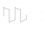
Actually, the waveform is not exactly symetrical??? See below???
I can look around "the playroom" a little more for another xfmr... Or, I have a Lincoln arc welder transformer in the basement???
I can also switch to a resistive load and see what happens with that
No change in the square wave response Actually, the waveform is not exactly symetrical??? See below???
I can look around "the playroom" a little more for another xfmr... Or, I have a Lincoln arc welder transformer in the basement???
I can also switch to a resistive load and see what happens with that
Attachments
Carpenter, You asked about PC based analysis Software. Well, I really can't tell you much but, first, you need a good sound card. I like mine but I haven't used half the apps that came with it or had the need for the excellent specs yet. But, it is a Creative Professional E-MU 1212m digital Audio System, in PCI(takes 2 slots). It's 2 Ch with 192kHz sampleing. It has 32 bit internal processing and mixing etc. with expandable capabilitiers for those who have to have a studio in their putor. It is 2 ch balanced input and ouitput with profesional level(+4dbm) or consumer level-(-10dbV) and 120 db S/N. A THD spec of .000Something etc... Kick A for a couple $100
Then you go google(I like http://www.dogpile.com/) Audio analysis software, and I have a True RTA package and the Right Mark Audio Analyser 5.5. One of them was free, the other I paid for. These things have oscilators, rms voltmeters, spectrum analysers, scopes, etc. etc. Built right into your putor go do some searchining here and in dogpile and read up a little
I'll have mine going in a coouple days I hope, I'll let you know more then... Ho Ho Ho
Then you go google(I like http://www.dogpile.com/) Audio analysis software, and I have a True RTA package and the Right Mark Audio Analyser 5.5. One of them was free, the other I paid for. These things have oscilators, rms voltmeters, spectrum analysers, scopes, etc. etc. Built right into your putor
go do some searchining here and in dogpile and read up a little I'll have mine going in a coouple days I hope, I'll let you know more then...
Ho Ho Hoflg said:Actually, the waveform
It is not an overshoot, but a "tilt"
I believe it is happening in LF, e.g. around 50Hz
I would not worry about at all, and be happy
Enjoy
Babowana, I know what your saying, I was hesitant to call it "overshoot" too But it is following the frequency and reducing it's "delay" or saturation or whatever unitl a few kHz and then it starts becoming a rounded rising edge all the way up to rolloff. The falling edge maintains a reasonable shape until it becomes the -rising edge??? What do you make of the capacitor looking curve at the top(positive) portion of the curve but a straiter looking ramp on the negative side???
I can take a few shots in the dark, the "shotgun" method??? I'm going to change the output E cap to a bigger low ESR type. The one that's in there is scavanged from an old peice of equipment??? Also I might try some damping??? A 100 ohm across the choke or to GND???
I'm sure after I've floundered around a little, N.P. will send a few of his words of wisdom this way (Pls. Nelson). I have a few places to look for idea's first... And then, I have these 2, 27.4 ohm(13.7 in ll) 75W R's I can plug in to verify the basic amp topology without all the L is good...
Oh,,, BTW Fuling, That was the 195T5 or the 195T10 Hammond unit I was looking at $$$ http://www.hammondmfg.com/195.htm
John, I havent seen any center taped units??? But, can you do the square wave thing with your system and see it on the scope???
But it is following the frequency and reducing it's "delay" or saturation or whatever unitl a few kHz and then it starts becoming a rounded rising edge all the way up to rolloff. The falling edge maintains a reasonable shape until it becomes the -rising edge??? What do you make of the capacitor looking curve at the top(positive) portion of the curve but a straiter looking ramp on the negative side???I can take a few shots in the dark, the "shotgun" method??? I'm going to change the output E cap to a bigger low ESR type. The one that's in there is scavanged from an old peice of equipment??? Also I might try some damping??? A 100 ohm across the choke or to GND???
I'm sure after I've floundered around a little, N.P. will send a few of his words of wisdom this way (Pls. Nelson). I have a few places to look for idea's first... And then, I have these 2, 27.4 ohm(13.7 in ll) 75W R's I can plug in to verify the basic amp topology without all the L is good...
Oh,,, BTW Fuling, That was the 195T5 or the 195T10 Hammond unit I was looking at $$$
http://www.hammondmfg.com/195.htmJohn, I havent seen any center taped units??? But, can you do the square wave thing with your system and see it on the scope???
Unfortunately, I don't have a square wave generator; the old heathkit beast died in its sleep. I had to download a 1K soundwave file from iTunes. It did the trick.
Oh, did it ever:
Now for the bad news: my electronic x-over doesn't have symmetrical outputs; the negative side is one-third the voltage of the hot lead. Darn. It has a direct impact on my ZV7--and to think it still sounds so good.
If TDM can't correct the problem, I may be in the market for a DIY electronic x-over. Come to think of it, I'm going to build one anyway.
And if that weren't bad enough, the Aphex single-ended in/balanced out unit is not so balanced. There is no negative lead at all! I wrote them a seriously direct note with regards to false advertising.
Now, I'm also in the market to build a phase splitter.
Ahhhh, so many projects...
John
Well John, I had my share of ignorance and stuff too. I've had my scope on the AC setting all this time and it really dosen't like a low freq square wave so much... Still getting used to it. I hooked up 13.7 ohms of resistor load and cranked the supply up to about 55V and set the scope on the DC settling and it does alot better... But there is still the slightest bit of this tilt still there??? And, the high freq rounding is still there... 10K dosent look so good
So
Back to the L's I guess
Did you measure your x-over connected to your ZV7? Maybe you should try unloaded or thru a known, or resistive load. You've been debuging and modifying alot with the ZV7 and maybe it is pulling something down???
So
Back to the L's I guess
Did you measure your x-over connected to your ZV7? Maybe you should try unloaded or thru a known, or resistive load. You've been debuging and modifying alot with the ZV7 and maybe it is pulling something down???
After a little thinking and re-reading the ZV7 article, it is just likely that I should expect the performance my ZV9-L is getting???
Nelson experienced low frequency "saturation" characteristics even though ZV7-T cancels the DC field in the inductor. My prototype dose not. And, I have not done THD measurements that may be somewhat comparable to his graphs. I have only wittnessed the squarewave performance, however revelavent... When I loaded my prototype with 13.7 ohms of R, I saw good low frequency results.
Nelson had good mid-band performance. I actually seem to also. The squarewave looks the best from 1-5kHz.
Nelson also experienced higher freq distortion with his L loaded experiment. Well, althought I called it rounding of the squarewave, it is higher frequency distortion
But with the R load, why do I still have high freq rounding of the leading edge of the squarewave
As far as I understand,
the rounding edge is due to the internal capacitance
The rounding indicates that the frequency is approaching
to the critical frequency, which might be 100kHz or above
And, we could use the rounding edge to estimate
the upper critical frequency, by reading the rise time
the rounding edge is due to the internal capacitance
The rounding indicates that the frequency is approaching
to the critical frequency, which might be 100kHz or above
And, we could use the rounding edge to estimate
the upper critical frequency, by reading the rise time
- Status
- This old topic is closed. If you want to reopen this topic, contact a moderator using the "Report Post" button.
- Home
- Amplifiers
- Pass Labs
- L Loaded ZV9 Help???