Hi, flg
I don't know well.
If the amp is an equivalent as one unit, it forms one set, or another,
of internal resistance and capacitance (and inductance?), which makes
the square wave of "tilt" at low frequency and "rounding edge"
at high frequency. I don't know how to calc the R and C values.
The lowering feedback resistor might affect the internal resistance.
Why not try to have an experiment?
Will be informative for the thread readers, too
🙂
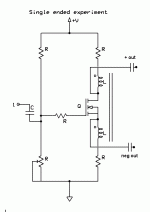
I had mentioned using a center tapped choke in this configuration on my ZV7 thread the other day.
Little did I know, someone had beat me to it.😀
You would take your voltage from the drain and source pins when substituting an FET for the valve.
Just for kicks, I might try this experiment tomorrow. I have a Plitron 1000 V/A tranny and a whole stack of FETs quaking in the corner.

Someone smell smoke?🙂
Little did I know, someone had beat me to it.😀
You would take your voltage from the drain and source pins when substituting an FET for the valve.
Just for kicks, I might try this experiment tomorrow. I have a Plitron 1000 V/A tranny and a whole stack of FETs quaking in the corner.
Someone smell smoke?🙂
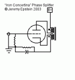
Fuling said:Carpenter: That topology requires an airgapped inductor to work.
topology shown with tube doesn't require gap, ordinary PP choke or xformer can be used,just because canceling effect of two current circs.
anyway,do you need AC feedback in cathode circ,that is another issue.
big cap can be handy there
This topology is commonly refered to as "split load" in the tube world, and the inductor does indeed require an airgap.
I might be wrong, but I´ve read a lot of discussions on this exact topic and they all come to the conclusion that the inductor must have an airgap.
You can of course cancel the DC by connecting one of the windings out of phase, but that would also cancel the signal.
I might be wrong, but I´ve read a lot of discussions on this exact topic and they all come to the conclusion that the inductor must have an airgap.
You can of course cancel the DC by connecting one of the windings out of phase, but that would also cancel the signal.
Fuling said:This topology is commonly refered to as "split load" in the tube world, and the inductor does indeed require an airgap.
I might be wrong, but I´ve read a lot of discussions on this exact topic and they all come to the conclusion that the inductor must have an airgap.
You can of course cancel the DC by connecting one of the windings out of phase, but that would also cancel the signal.
sorry fuling,I didn't clicked on little pic (to wiev it in another window) and I just presumed that winding are in cancelling arrangement (and .yes I know Iron Concertina) ......so -I just presumed that sorta McIntosh circ was drawed
besides that mistake,I commented just toob variant
what you sayed - worths for both pics sent by carpenter.
gap is a must
I have lowered the input and feedback resistors in my ZV9-L and the results were as expected. I had a 10K input and a 75K feedback resistor. I kept the same ratio but, I went with a 5K input and a 37.5K feedback R. The10kHz squarewave looks pretty good now. The -3db on the upper end pushed up to about 136kHz😀 😀 😀
There did not seem to be any apparent affect with the inductors ability to maintain "square" waves at the low end. Still trying to work out what to do there 😕 😕 😕 I have plentty of air but can't afford many hundred feet of magnet wire right now
Everything seems to be quite stable otherwise... It's probably about time to plug in a speaker😀
You can of course cancel the DC by connecting one of the windings out of phase, but that would also cancel the signal.
I was trying to figure out how to cancel the dc saturation by connecting out of phase; apparently I didn't draw it correctly. I do this on my ZV7, how come the AC cancels out with this?
Thanks for the comments, fellows,
John🙂
Excellent work, flg. I have to rush out but will study your post in an effort to learn. Thanks.
If your ZV7 is built as shown in Nelsons article it´s a balanced design, right? (us tube guys would definitely call it push pull).
Having two active devices working in balanced mode with a centretapped inductor is entirely different from having one active device working in SE mode even if the inductor is split between the drain and the source.
Having two active devices working in balanced mode with a centretapped inductor is entirely different from having one active device working in SE mode even if the inductor is split between the drain and the source.
Yes, that's right Fuling. Carpenter has it much easier with his design I would say. But, I'm really not convinced all my problem is DC useing up all the available flux density(or whatever I should call it) and bringing the signal closer to saturation. I'm going to play with higher inductance and more gain next, on the premise that all the calculations are based on sine wave conclusions. Maybe music isn't square waves either but if I can do a descent square wave, music should be easy. Even Jimi Hendrex music😀 I can also increase my load R substantially to simulate the effects of really large inductors without actually using them. Remember that THD tests are only done with sign waves also. I have tried cutting my Iq in 1/2 and I did not see enough of a change(except for lower gain) 
Have you been part of the Pathos thread and the Choke Loads for ZEN Amps thread??? Based on some of that info 100mH inductor should produce good sound into the low freq range... I think the units I've tryed are double or more, that inductance???
Have you been part of the Pathos thread and the Choke Loads for ZEN Amps thread??? Based on some of that info 100mH inductor should produce good sound into the low freq range... I think the units I've tryed are double or more, that inductance???
flg said:I have lowered the input and feedback resistors in my ZV9-L and the results were as expected. I had a 10K input and a 75K feedback resistor. I kept the same ratio but, I went with a 5K input and a 37.5K feedback R. The10kHz squarewave looks pretty good now. The -3db on the upper end pushed up to about 136kHz😀 😀 😀
Wow
Plzed with good news
Make budget for a supertweeter 😀
I've performed a few more tests on the ZV9-L idea which may intrerest a few others. I tried connecting my 800VA toriod as the load, previously tested in the 115V connection, in the 230V connection. My expectation was that I would see the effects of the >1H inductance (4X the 115V connection) improve the output wave shape or the saturation effects worsen. It appeared that the saturation effects worsened much more than the increase in induction helped.
I also disconnected the feedback to take a look at open loop gain etc. 😀 Open loop gain, at 1kHz, with Iq of about 2.2A and a 7.5 ohm output load with 1Vp-p input, seems to be about 20 with my best EI laminated inductor as the load, and just short of 15 with my 13.7 ohm R as a load resistor.
I was running a gain of about 7 (16db) and about 10db of feedback, if my guess is correct...
flg said:which may intrerest a few others
Few others are having real values
and they are VIPs
😀
That buffer looks so familiar😉 I ran 442K on the feedback resistor and 147K to ground at the buffer's gate. The only difference is the 1uF blocking cap I have on the input. I also biased the buffer up with a 571 ohm source resistor.
I notice you're using an electrolytic and non-polarized cap in the power filtering stage above the buffer's source resistor. What does the n-p do?
I'm still digesting the rest of your circuit. Pretty picture!
John🙂
I notice you're using an electrolytic and non-polarized cap in the power filtering stage above the buffer's source resistor. What does the n-p do?
I'm still digesting the rest of your circuit. Pretty picture!
John🙂
another thing: you placed a resistor to ground at the buffer input prior to the 10K gate resistor, whereas I ran my 147K to ground after. Is there a difference? I also ran 221 ohms in place of your 10K.
I'm all eyes.😀
John
I'm all eyes.😀
John
Yes, I think the R to ground at the input is likely unecessary. There is a path to ground through the feedback R and 100 ohm. If you don't give a MOSFET gate a path to GND it will float around... The tinyest leakage current will pull it to a DC GND with that R, but as I said, it's got a path. Your amp has a high DC voltage at the output, not a exactly a DC path to GND...
The R before the 10K is actually forceing the 10K to be the major contributor to the input impeadance. If it were after the 10K, the input voltage would be 9/10ths of it's level and the ratio of the 10K and 100K(F.B.) would have to share that impeadance(and signal current) and it would effect gain. Your amp has a DC current from the output looking for GND and it is part of a voltage divider from the output to GND. Therfore it sets the gate voltage of the buffer and you probably should have it there. A few posts ago I mentioned that. All those Rs in that area have to be considered for gain and follower bias etc. I did not like messing with it when I was playing with that design. I don't have to mess with the DC from my output, it's after the output cap, no DC😀
The 221 ohm, well, I remember looking at your circuit once and seeing huge gain(due to the 221 ohm). I thought you figured that out though??? In my circuit the 100k(F.B.) divided by the 10K determines the overall gain. No other considerations of output DC are involved... and The preamp or whatever basically see's The 100K in paralell with the 10K for an input impeadance to the amp.
So, what does your current schematic look like hey we should be in the other thread with this😀
The R before the 10K is actually forceing the 10K to be the major contributor to the input impeadance. If it were after the 10K, the input voltage would be 9/10ths of it's level and the ratio of the 10K and 100K(F.B.) would have to share that impeadance(and signal current) and it would effect gain. Your amp has a DC current from the output looking for GND and it is part of a voltage divider from the output to GND. Therfore it sets the gate voltage of the buffer and you probably should have it there. A few posts ago I mentioned that. All those Rs in that area have to be considered for gain and follower bias etc. I did not like messing with it when I was playing with that design. I don't have to mess with the DC from my output, it's after the output cap, no DC😀
The 221 ohm, well, I remember looking at your circuit once and seeing huge gain(due to the 221 ohm). I thought you figured that out though??? In my circuit the 100k(F.B.) divided by the 10K determines the overall gain. No other considerations of output DC are involved... and The preamp or whatever basically see's The 100K in paralell with the 10K for an input impeadance to the amp.
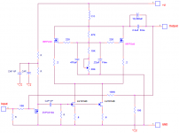
So, what does your current schematic look like
hey we should be in the other thread with this😀I'm having a lot of fun reading your posts. They're quite informative.🙂
I have no immediate response, 'cause I'm chewing on the meat of the subject.😀
John
I have no immediate response, 'cause I'm chewing on the meat of the subject.😀
John
- Status
- Not open for further replies.
- Home
- Amplifiers
- Pass Labs
- L Loaded ZV9 Help???