 Look into my eye....
@JT how do you have the output from the SIT-3 connected to the QA401? Do you have it connected on both the IN+ and IN- or are you just connecting to one of those? I think you need to use shorting plug if you aren't connecting both IN+ and IN-
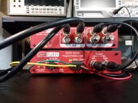
That's a huge part of the issue... the connections are not clear to me. Especially going from the Q451. There are only two outputs there and four on the Q401. From what I gather the ground from the Q451 needs to be split before going to the Q401 and then the pos side goes to the center pin of Pos and the ground goes to the inside pin of the Q401 like a plus and minus voltage situation. I think this is what they want you to do, but very little in the way of help, nothing in the way of someone to call.
Also, for the output from the 401 to the input of the amp, same thing split off the + and ground and treat them like + and - coming out of the 401.
From what little I understood from reading they are doing a signal 180 Out for reducing noise.
I love to see more hookup help on this animal. If someone is around Rockord, Il give mea shout, I could use help.
Try the QA forum on their website. There is also some good information in the blog on the 401/451 combo:
Introducing the QA451 – QuantAsylum
Based on the connection image in the blog, your connections look right.
Matt from QA also posts here as well - his username is QAMAtt or something like that. There is a QA401 thread he posted in and there are other helpful folks from QA who post in the tools forum.
Last edited:
This video shows the QA450 and 401 used together:
QuantAsylum Tractor, QA401 and QA450 - YouTube
Hopefully it'll help you with the setup.
QuantAsylum Tractor, QA401 and QA450 - YouTube
Hopefully it'll help you with the setup.
In the blog post, they mention the simplification in connections for the 451 vs the 450. You don't need separate IN- connections with the 451 so just 2 connections needed (451) instead of 4 (450):
The system block diagram between the QA450 and QA451 is unchanged. Below you can see the diagram for the QA401 and QA450. When using the QA451, you won't need the ground wire on the DC switch connector, and the outputs on the QA451 need a single BNC per channel instead of two. These both make for slightly simpler cabling for test installations.
Do you have a lottery VFET amp to compare the SIT-3 to? Are they more similar than different (SE/PP - one went north, one went south but both end up in Rome?)
Ya, but there isstill 4 inputs on the QA401 and from what I read it uses them to invert one for some noise canceling thinggoingon and it can't do that unless, I split output from the 2 to 4 going into the 401.This may be wrong, but otherwise why have 4 inputs on the 401 if only 2 are ever used? As it the + side of left and right used and the neg side are terminated.
And no, I was not one of the lucky ones who won.
And no, I was not one of the lucky ones who won.
I believe in my testing skills not at all, but I will get there eventually. Funny thing is, I never went down this road because I know what sounds good to me. The exception to that would be extensive in room testing for acoustics. That is huge and with challenging rooms makes it at least as important as anything in the chain.
I want to learn the tools so it may help me decide what to build according to what I like and the other is to build a new amp and do some basic testing to make sure things are as the should be or to troubleshoot.
Maybe the shelf is the best place for the Quant unless you are looking for an issue you defined by listening.")
I want to learn the tools so it may help me decide what to build according to what I like and the other is to build a new amp and do some basic testing to make sure things are as the should be or to troubleshoot.
Maybe the shelf is the best place for the Quant unless you are looking for an issue you defined by listening.


I'm still working with the test equipment, but I changes load Rs and have mostly shielded the wire with one exclusion I will deal with tomorrow. I'm getting more solid in the comfort with the measurements I'm getting.
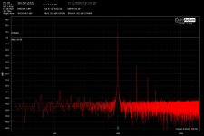
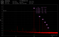
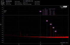
The first image will be a repeat of the one above before I shielded things up. The second is all, but one and I don't think it's going to change much, as the Badger tested with the same setup is looking good and the THD numbers are low with the same setup...
What else changed? New load resistors going back to the QA451 as the load. Replaced all wires with shielded TP save a ground that I will do tomorrow and report on any data change.
What's you point JT? I was an old school machinist and I wish I had a pro I could drop it on their bench and print out the numbers, so I would know what I know, or don't know... you know?
Obviously I digress, but what I do know is that with current knowledge and tools, the SIT-3 is running about 0.42 % THD at 1.1W into 8ohms at 1khz.
Attachments

Last edited:
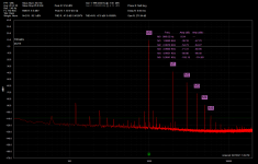
Did some more testing after i shielded everything. I'll keep looking... I will work through/refine my testing procedure, but as of now this is what it is. At 1W into 8ohms at 1KHz I'm at 0.38% Also the SNR is higher than John measured too, though his equipment is much better than mine as are his testing skills.
Attachments
Last edited:


- Home
- Amplifiers
- Pass Labs
- SIT-3