At what point an "amps" becomes a heater?? I suppose, at a certain point, would one reach for that ON switch just to heat up the room? Strictly speaking, it doesn't really matter what the heating element is... especially if it makes sweet music. Would the heat generation be a primary purpose... like "a heater, with benefits"? ")
Yes, definitely a room heater, so it's a winter only amp for me. I have electric heat so whether the heat comes from electric base boards or from nearly 200W dissipating from each mono block, the electricity cost is the same. I will be reconfiguring my BAF2015 THF-51S amps to follower configuration. They have already provided heat and music for two winters. They are fan cooled so that also circulates the air for more even cooling of the room.
At what point an "amps" becomes a heater??
Yamaha B-1,
 after about half hour, it would challenge the hand touch. Hotter than any of my Class A amps
Now I need one of these Tokin amps so I have something to use in summer time
Last edited:
Yes, definitely a room heater, so it's a winter only amp for me. I have electric heat so whether the heat comes from electric base boards or from nearly 200W dissipating from each mono block, the electricity cost is the same. I will be reconfiguring my BAF2015 THF-51S amps to follower configuration. They have already provided heat and music for two winters. They are fan cooled so that also circulates the air for more even cooling of the room.
+1 following with much interest.
Thank you for sharing the progress!
Many thanks to Ben Mah for doing the research. I see no alternative than to follow his steps and build both topologies.
So i did and patiently listened to each configuration for a few days using as wide a program material as possible. Only listened to my Wilson WP7 speakers as my other speaker setup is more complicated. The common source circuit was fed from a SS preamp while the source follower was tried for comparison with the SS pre but most of the listening was done with a 6H30 transformer coupled pre.
1. Common source. A BAF2015 in CCS mode.
2. Source follower with the speaker load returned to ground
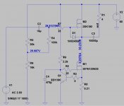
3. Source follower as shown on the circuit below.
4. Same source follower but powered from a capacitance multiplier.
None of the four provides even remotely tolerable bass with the Wilsons which is neither surprising, nor a problem. Only a push pull amp can do bass with these speakers.
1. Provided some real entertainment with some music but was ultimately a proper "Picasso" amp.
2. Yay, low distortion, how much i missed you
Nice but sleepy and slow.3. A big surprise here. Andrea had it right returning the speaker at the drain. Of course there is no PS ripple attenuation at all, so mild but annoying hum. The midrange is very alive. Microdynamics are great. The highs are divine. Less bass weight than the first two and perhaps worse bass too.
4. No hum whatsoever but a little is taken away from the midrange magic. Not too bad really.
At this stage it seems desirable to reduce the hum as much as possible by CLC. Currently it is 33mF - 1ohm - 33mF.
Not entirely happy with the outcome. Having a speaker terminal at 60v above ground is asking for trouble. Especially at my age of forgetfulness.
The SITs in both channels are a bit dissimilar. One has a dominant 2nd, the other a 3rd. Both have an equal amount of third but the one has more 2nd.
EDIT: Currently there is a dedicated bias source with a separate transformer. Took off the protection zener as i clearly prefer the sound without it.
Attachments
Last edited:
A CLC filter can reduce hum to the millivolt level. I use that configuration in my builds.
I really like my 2SK180 source follower with choke load. My 2SK180s are unmatched and one also has lower 2nd harmonic, but my Luminaria preamp distortion is dominant so it's not a problem.
I have a BAF2015 with THF-51S common source and for the midrange and highs, I find the lower distortion of a source follower preferable as well. I like it a bit more for the lower frequencies, though.
The similarity has a known cause imho.
The mu is slightly different.
What I would try is a different current and Vb for both sides, so no common supply.
And then also maybe play with that ‘tap’ which does vary the harmonic structure a bit I understand.[But have not done yet]
The mu is slightly different.
What I would try is a different current and Vb for both sides, so no common supply.
And then also maybe play with that ‘tap’ which does vary the harmonic structure a bit I understand.[But have not done yet]
Analog_sa, a couple of suggestions along the same lines of what triode_al suggested:
1. Try a different Vds and Iq for the SIT. I have found that higher voltage and lower current worked for me for better harmonic distortion profile, say 33 to 35V and 2.2 to 2.5A for the 2SK180. The voltage drop across the CCS and SIT will no longer be equal. I did that with my common source BAF2015 amp.
When I do my build I will test and vary parameters if I do not like the initial harmonic distortion profiles.
2. Add some resistance between the CCS and SIT and take the speaker output from the middle of the resistance (mu follower). That will change the harmonic distortion profile. The speaker out location between the resistor group can be varied also. However I am not sure whether your CCS will work in conjunction with resistance as a mu follower. The CCS with optocoupler in my schematic in post #1 will.
If you are concerned with the voltage at speaker ground, you can change the polarity of the power supply as I have done in my schematic.
Thanks for all the suggestions in the last few posts. I was slowly drifting towards similar conclusions but your suggestions will speed this up.
A mu-follower is not something i am inclined to try out. It erodes the concept of a SE stage and trades a supposedly better harmonic profile against a higher total amount of harmonics. And it raises the output impedance. I don't really mind a dominant third. For me having similar harmonic profiles in both channels seems more important.
A mu-follower is not something i am inclined to try out. It erodes the concept of a SE stage and trades a supposedly better harmonic profile against a higher total amount of harmonics. And it raises the output impedance. I don't really mind a dominant third. For me having similar harmonic profiles in both channels seems more important.
Thought also of the following. If the earth is as said, add a V+ of say 25 volts.
Then with a strong JFET, that has a high Idss so to say, then you need a large negative bias on the JFET, something like a few volts too. Now you have 8 volts in the sim, but if it is 2-4 volts, having a source follower this way is great too. Connect the source load to the most negative rail.
If you have succees the secret element of Passium will be in the system.
Passium is an element in the periodic system that opens up the fourth dimension.
Then with a strong JFET, that has a high Idss so to say, then you need a large negative bias on the JFET, something like a few volts too. Now you have 8 volts in the sim, but if it is 2-4 volts, having a source follower this way is great too. Connect the source load to the most negative rail.
If you have succees the secret element of Passium
will be in the system.Passium is an element in the periodic system that opens up the fourth dimension.
Last edited:
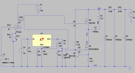
Fixed the hum issues when the speaker return goes to V+ with the addition of another PS cap and some resistance. Zero hum from any practical pov now.
Got the two channels to have identical distortion profiles and currently thd is set to a minimum. 3rd is very slightly lower than 2nd. The distortion is a ridiculously low 0.0069% @ 0.4W/4ohms. For reasons that are probably obvious but never the less escape me varying Vgs allows to balance between 2nd and 3rd within very wide margins.
Changing whether the source is grounded on the negative or positive rail is not the same. It appears to me in one case the signal is passing through the last PS cap. Listening tests were quite interesting with some deliberations within the first half an hour but eventually source ground went where it belonged, to the negative PS terminal.
Here is a more or less detailed circuit of what i have. Regulator is a 317HV and the mosfet a 140N20
Got the two channels to have identical distortion profiles and currently thd is set to a minimum. 3rd is very slightly lower than 2nd. The distortion is a ridiculously low 0.0069% @ 0.4W/4ohms. For reasons that are probably obvious but never the less escape me varying Vgs allows to balance between 2nd and 3rd within very wide margins.
If you are concerned with the voltage at speaker ground, you can change the polarity of the power supply as I have done in my schematic.
Changing whether the source is grounded on the negative or positive rail is not the same. It appears to me in one case the signal is passing through the last PS cap. Listening tests were quite interesting with some deliberations within the first half an hour but eventually source ground went where it belonged, to the negative PS terminal.
Here is a more or less detailed circuit of what i have. Regulator is a 317HV and the mosfet a 140N20
Attachments
I see you have added CRCRC to the power supply. That will definitely reduce the hum. In my single ended amplifiers I use a CLC power supply and that works really well. I hear no hum at all out of my 102dB speakers.
If you look at my schematic in post #1, you will see what I meant about power supply polarity. I also like that I do not need to add a separate bias supply.
If you look at my schematic in post #1, you will see what I meant about power supply polarity. I also like that I do not need to add a separate bias supply.
Boyz dealing with some serious hardware, these days

not just hardware but are throwing the gauntlet down with serious and simple designs!
Good job Ben!If you look at my schematic in post #1, you will see what I meant about power supply polarity. I also like that I do not need to add a separate bias supply.
Тhe supply polarity is relative and unimportant. The important bit is whether you connect the speaker load and source ground to positive or negative rail. Bias can be derived from the main power supply in either case.
After exhaustive listening tests i have established that returning the speaker to the positive rail is good, while connecting the source ground to the positive rail is not. A separate bias power supply also sounds better to me.
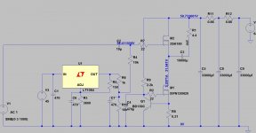
A next logical step would be to integrate a tube gain stage into this as such integration will make possible to remove the input capacitor and use the gain stage transformer secondary as means to apply bias. Otoh, already pushing towards 20kg/channel...
The bias circuit can also be simplified by moving the pot from output to Adj pin.
Attachments
Analog_sa, Elvee has a mod to lower the noise of LM317 by ~30dB in D-Noizator: a magic active noise canceller to retrofit & upgrade any 317-based V.Reg.. I believe the trick allows TO92 LM317L to be usable as a low impedance and low noise bias reference.
Thanks, Greg.
Analog_sa, there are many ways. It's all about the fun of diy, exploring possibilities. I will be trying a high voltage SIT single ended common source gain stage once I receive my long awaited Russian SITs.
WBS, you have mistaken me for someone much more capable. I have been to Burning Amp (2019), but I did not bring any electronics. Unfortunately it is very difficult to transport bulky and heavy amplifiers long distance and across borders. But I do hope to be able to attend Burning Amp this year.
Analog_sa, there are many ways. It's all about the fun of diy, exploring possibilities. I will be trying a high voltage SIT single ended common source gain stage once I receive my long awaited Russian SITs.
WBS, you have mistaken me for someone much more capable.
I have been to Burning Amp (2019), but I did not bring any electronics. Unfortunately it is very difficult to transport bulky and heavy amplifiers long distance and across borders. But I do hope to be able to attend Burning Amp this year.- Home
- Amplifiers
- Pass Labs
- Single Ended Tokin SIT THF-51S Common Drain Mu Follower Amplifier, 45W?