Guys, I have updated the app. For now, it's only for 2sk170, but I will add more JFETs soon.
The Vto has been adjusted so the transconductance curves from the 2sk170 datasheet and the app look identical. If you use this model in LTSpice, specify Vds at 10V, Vgs equal to Vto you will get Id at around 100nA, so Vto is treated by LTSpice like Vgs(off), by the Toshiba definition.
BTW I think the Vgs(off) as a function of Idss plots in Toshiba datasheets are wrong, also these for 2sk170 are almost identical to these for 2SJ74, if you look at transconductance curves you will notice that it's impossible.
But there is a problem with beta in LT Spice, it should be calculated using Idss, Vto, lambda and Vds from the equation below:
beta = Idss / (Vto2 * (1 + lambda * Vds) * tanh(Vds))
But with beta calculated from this equation, you will never get Idss at the specified level, always lower.
So I created a compensation, measured Idss at three points that drew the parabola and adjusted beta. Now you will get the correct Idss in LTSpice.
I don't know why LTSpice interprets beta this way, maybe some time ago they did a mistake, and they are not going to fix it as the new version would work differently with the same models/simulations. or maybe I am missing something 🙂
PS: it doesn't work in IE
Last edited:
The new version has the same link?
the same, I don't specify expiration in HTTP header but ctrl-R should refresh the page 🙂
If you measure a real JFET, then plot its log(Idrain) versus Vgs, across six orders of magnitude of Idrain, from 1E-8 amps to 1E-2 amps [or wherever Idss happens to be], you'll find that the measured data does not fall upon a straight line whose slope matches a quadratic relationship.
However, SPICE uses a quadratic model.
So you'll have to decide which parts of this plot you want to focus upon. Where must the quadatric model fit the measured data the tightest (in your judgement)? Where are you willing to accept not such a great fit between model and real device?
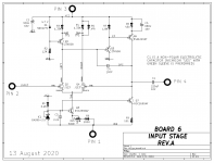
My most recent JFET circuit is shown below. A quick analysis indicates that these JFETs spend all of their time working in a much narrower range of maybe one or two orders of magnitude of Idrain. So to simulate this circuit I only want good agreement between model and real device, on a small piece of the log(Idrain) vs Vgs curve. So there's a much better chance of getting a pleasing agreement.
But: just how representative is this circuit? Just how big a crackpot am I? Judgement calls.
_
However, SPICE uses a quadratic model.
So you'll have to decide which parts of this plot you want to focus upon. Where must the quadatric model fit the measured data the tightest (in your judgement)? Where are you willing to accept not such a great fit between model and real device?
My most recent JFET circuit is shown below. A quick analysis indicates that these JFETs spend all of their time working in a much narrower range of maybe one or two orders of magnitude of Idrain. So to simulate this circuit I only want good agreement between model and real device, on a small piece of the log(Idrain) vs Vgs curve. So there's a much better chance of getting a pleasing agreement.
But: just how representative is this circuit? Just how big a crackpot am I? Judgement calls.
_
Attachments
It's Friday and I am quite tired now but... are you saying that for small Id currents the dependency between Vgs and Id is not quadratic in real JFET?
That the below equation does not apply to a small range of Id?
Id = Idss*(1 − Vgs/Vgs(off))2
That the below equation does not apply to a small range of Id?
Id = Idss*(1 − Vgs/Vgs(off))2
OK, I got a little bit of understanding of how LTSpice calculates DC relations between Idss, beta, lambda, Id, Rd, Rs, etc.
I have simplified the model and started analyzing it.
First, let's create a simple circuit in LTSpice:

...and even simplier model:
The Id (equal to Idss in this case) we calculate from the equation:
Idss = beta*Vto2
...and we get exactly 10mA in our simulation in LTSpice.
But the "real-life JFET" has also lambda, the channel length modulation,
the value that describes the change of Idss as a function of Vds in the
saturation region. If we add lambda to the model, for example, 0.005 (1/V):
The Idss in LTSpice is now 10.5mA, because:
Vds = 10V
Idss = beta*Vto2*(1+ lambda*Vds)
Also "real life JFET" has Rs - Source Ohmic resistance:
And this Rs can be treated as a source resistor.

I have looked for an equation that calculates Id for a given beta, Vto, lambda and Rs...
I haven't found one in the whole internet... so had to find it myself, because:
Id = Is = Idss*(1-Vgs/Vp)2
we can assume that the source current Is is equal the drain current Id as the gate current is super small.
If we multiply both sides of the equation by Rs we get:
Vgs = -Idss*Rs(1-Vgs/Vp)2
so we need to modify this equation to get Vgs, so:

The equation is super simple:
Vp = -Vto
Idss = beta*Vto2*(1+ lambda*Vds)
Vgs = -(2*Idss*Vp*Rs+Vp2-sqrt(4*Idss*Vp3*Rs+Vp4))/(2*Idss*Rs)
Indeed for a given in model: beta, Vto(-Vp), lambda and Rs we get exaclty the same value, in LTSpice.
and Id:
Id = Vgs / Rs;
but then... "real life JFET" has also Rd... drain ohmic resistance that can be treaten as the drain resistor...
you know guys... I will let you know when it will be done... 😀
I have simplified the model and started analyzing it.
First, let's create a simple circuit in LTSpice:
...and even simplier model:
Code:
.model 2sk170 NJF(Beta=40m Vto=-0.5)Idss = beta*Vto2
...and we get exactly 10mA in our simulation in LTSpice.
But the "real-life JFET" has also lambda, the channel length modulation,
the value that describes the change of Idss as a function of Vds in the
saturation region. If we add lambda to the model, for example, 0.005 (1/V):
Code:
.model 2sk170 NJF(Beta=40m Vto=-0.5 Lambda=5m)Vds = 10V
Idss = beta*Vto2*(1+ lambda*Vds)
Also "real life JFET" has Rs - Source Ohmic resistance:
Code:
.model 2sk170 NJF(Beta=40m Vto=-0.5 Lambda=5m Rs=5)I have looked for an equation that calculates Id for a given beta, Vto, lambda and Rs...
I haven't found one in the whole internet... so had to find it myself, because:
Id = Is = Idss*(1-Vgs/Vp)2
we can assume that the source current Is is equal the drain current Id as the gate current is super small.
If we multiply both sides of the equation by Rs we get:
Vgs = -Idss*Rs(1-Vgs/Vp)2
so we need to modify this equation to get Vgs, so:
The equation is super simple:
Vp = -Vto
Idss = beta*Vto2*(1+ lambda*Vds)
Vgs = -(2*Idss*Vp*Rs+Vp2-sqrt(4*Idss*Vp3*Rs+Vp4))/(2*Idss*Rs)
Indeed for a given in model: beta, Vto(-Vp), lambda and Rs we get exaclty the same value, in LTSpice.
and Id:
Id = Vgs / Rs;
but then... "real life JFET" has also Rd... drain ohmic resistance that can be treaten as the drain resistor...
you know guys... I will let you know when it will be done... 😀
I'm egg-cited!! 😛Ripson,You are a Real Easter Egg...!
The app is back online, it works, and it's very precise.
So beta is adjusted depending on Vto, Lambda, Rd and Rs so when you take the model, plug it into LTSpice you will get desired Idss with the precision of a few decimal points. Idss was specified at standard Vds = 10V.
I haven't been using integrals and differentials for years, I just don't remember them, so instead of simpler equations inside the app I have used loops, but they iterate less than 100 times doing something similar to binary search so the result is instant.
New models coming soon, if you think there are mistakes in the models (params other than beta and vto) please let me know I can adjust it.
I am happy that I built it, it gave me a better understanding of how LTSpice interprets the JFET models.
Last edited:
...I have looked for an equation that calculates Id for a given beta, Vto, lambda and Rs... I haven't found one in the whole internet... so had to find it myself ... 😀
SPICE program code is open-source. For example: Spice
Also: SpiceSharp/SpiceSharp/Components/Semiconductors/Junction FETs at master * SpiceSharp/SpiceSharp * GitHub
Oh thank you Ripson!
So many new J-Fets included!
Wonderful!
Gerd
You're welcome 🙂 I wanted to create a universal generator that calculates beta based on Idss, Rd, Rs, lambda and Vto... but Vto is problematic, you have to get two points from the transfer curve and then calculate Vto for a specific Idss, so it's not straightforward. But I hope you find the predefined models useful.
fwiw, I once fitted the parameters of the SPICE jfet models to curves I took from a set of BF862. You'll find my musings here.
Cool 🙂 I have added BF862, I've limited Idss between 10 and 25mA as per NXP datasheet. Also, Vto defined based on the spec from the year 2000. This JFET is very much like 2sk170 in terms of the transfer curve, much higher lambda hence Vds has higher impact on Id in the saturation region.
However, the transfer curves in the spec are for Vds=8V, not 10V so it might not be super reliable.
EDIT: I haven't tested it in LTSpice
Last edited:
There was no interest in this so I removed it from the server, it's back now., slightly modified.
now I calculate beta from the equation:
beta = idss / (vto * vto * (1 + lambda * vds) * tanh(vds));
Hi, could you please show where lambda comes from? I am trying to simulate 2SK68A in LT Spice but I think I am doing wrong. Where in the Output Characteristics graph sould I see? what values?
Sorry, I am kind of new with modeling.
Thank you
Yes, perhaps you can explain why some has increasing Beta with Idss, e.g. 2SK170;
and others have decreasing Beta with Idss, e.g. BF862, 2SJ74, ...
Thx,
Patrick
and others have decreasing Beta with Idss, e.g. BF862, 2SJ74, ...
Thx,
Patrick
That's what happens with best-fit coefficients for mathematical models of physical processes. Different people have different ideas of what set of tradeoffs is "best", especially in a multi-input, multi-output model.
Sorry guys haven't got notifications about these posts, I just read them now.
That might come from the assumption (possibly wrong) that Rd, Rs and lambda are constant for a particular JFET model (regardless of Idss). Based on the values that were present in the existing models I have calculated beta and Vto to get in LTSpice precisely adjusted Idss to a few decimal places.
If there is a known relation between lambda, Rd, Rds, and desired Idss I would change the equations and probably make a better app.
Yes, perhaps you can explain why some has increasing Beta with Idss, e.g. 2SK170; and others have decreasing Beta with Idss, e.g. BF862, 2SJ74
That might come from the assumption (possibly wrong) that Rd, Rs and lambda are constant for a particular JFET model (regardless of Idss). Based on the values that were present in the existing models I have calculated beta and Vto to get in LTSpice precisely adjusted Idss to a few decimal places.
If there is a known relation between lambda, Rd, Rds, and desired Idss I would change the equations and probably make a better app.
I had to make calculations based on the values specific to the particular JFET model. Lambda wasn't calculated, it was taken from the existing models I found.Hi, could you please show where lambda comes from?
- Home
- Amplifiers
- Pass Labs
- JFET model generator