some input xformer trickery
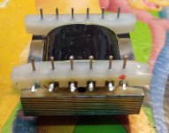
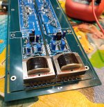
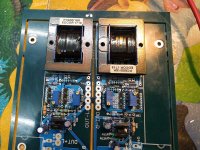
as already mentioned - with Cinemags there is some trickery necessary , to put them on pcbs
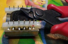
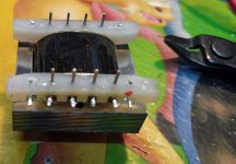
pins 1 and 2 are closer than other ones , so you know which pin 1 is - red dot on pictures
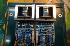
cut pins 1 , 6 , 7 and 12 , then you can mount Cinemags on pcb ; as you can see , on both channels pin 1 is near pcb edge
also pics of Edcors , Cheapskate Champions (one of cases where article is cheaper than shipping) - they're oriented with 180deg difference between channels ; pinout orientation pretty clear and straightforward , so no biggie there
as already mentioned - with Cinemags there is some trickery necessary , to put them on pcbs
pins 1 and 2 are closer than other ones , so you know which pin 1 is - red dot on pictures
cut pins 1 , 6 , 7 and 12 , then you can mount Cinemags on pcb ; as you can see , on both channels pin 1 is near pcb edge
also pics of Edcors , Cheapskate Champions (one of cases where article is cheaper than shipping) - they're oriented with 180deg difference between channels ; pinout orientation pretty clear and straightforward , so no biggie there
Attachments
Sissy does not like me 
Problem with right channel:
This time setting Iq for buffer was almost straight forward. I just didnt get offset to zero and had to increase Iq to 22mA. Trick could be to increase upper R27 to have more headroom?
Then inserted JP, but turning on Iq pot did increased (U over R0.1) from around 4mV to just 5.6 mV to the end of pot, offset increased to almost 15 Volts.
Got me a bottle of wine to the studio to celebrate stereo this night, but this must wait (stereo, not wine).
Will of course recheck da hole thing tomorrow. Its really not that i watch series while stuffing PCBs, but this time i´m troublemaker.
It´s late ZM, i´m happy for your thoughts in time : )
best
st
well , troublemaker or not , I'm sure you'll find what's the culprit
it could help if you post some pictures , if you don't find it straight away in the morning or so
regarding source resistance .... I did check about dozen or so JFet groups and in all cases 27R ll 100R pot combo was adequate ..... but it seems that switch to 39R ll 100R pot will cover all possible Idss cases
I did some editing of post #1 , will proceed .....
dunno did you got Babelfish M25 or straight SissySIT package ........ so polarity (type) of mosfet is important ..... same as proper orientation of 7805 - they aren't mounted same on L vs. R channel
i made that supernice cableends i saw in your pics, from soft wire with hard wire end, i used laquered 1,4mm, i of course sanded
them but they seem to be cold (soldered) even if solderpoint looks nice,
thats work for now : )
them but they seem to be cold (soldered) even if solderpoint looks nice,
thats work for now : )
i made that supernice cableends i saw in your pics, from soft wire with hard wire end, i used laquered 1,4mm, i of course sanded
them but they seem to be cold (soldered) even if solderpoint looks nice,
thats work for now : )
explain , what you mean - which cable ends I made ?
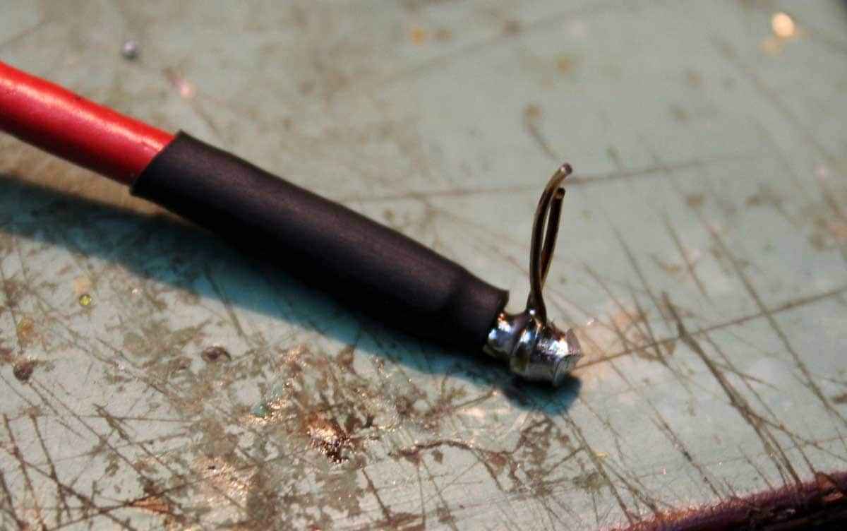
those shown in this very thread are nothing else than regular cables stripped on ends little longer , then covered with heatshrink - simply because I hate to see even slightly melting cable isolation ....... heatshrink is just even more shrinking , and still looks nice 🙂
ah, the i saw it different, i really hate to fix 1,5mm cable in tiny holes, so i took a superfine "Lize" from a cable, wound a hardwire peace at the end of the cable and soldered them together, sound comlicated or no good, but i show pics then, i like it
aha , I got it
you did same as I did on Papa's Koan M2 , pics in my blog ........ and probably everywhere
tip: for thick wires , I'm always using screwdriver-like solder tip , around 8mm long edge , temp. set at 380-400C
Papa’s Koan (M)2 , an amp for living room | Zen Mod Blog
you did same as I did on Papa's Koan M2 , pics in my blog ........ and probably everywhere
tip: for thick wires , I'm always using screwdriver-like solder tip , around 8mm long edge , temp. set at 380-400C
Papa’s Koan (M)2 , an amp for living room | Zen Mod Blog


mpf, you clever, mosfet orientation : ), gate is not on the edge (outside) on both PCBs, its on right side : ), haha, i´m so Spiegelbildfanatic i coud cry ;O
i´ll have party now, it works


i´ll have party now, it works
well , another confirmation case that ZM is not only one Knowing Station

write more - how it works ...
take care that you have (additional/flying) 100R gate resistor ditto on SIT gate
write more - how it works ...
take care that you have (additional/flying) 100R gate resistor ditto on SIT gate
Last edited:
have to correct ärrrrrgh LED brightness, dont feel comfortable with two different settings, soundwise, before i listen to it, after my episode here...is relaxing : )
- Home
- Amplifiers
- Pass Labs
- Babelfish M25, SissySIT - general building tips and tricks