cal , there is a massive first post in thread
be sure that you understand each and every line ........ or mistake can cost dearly
0R1/3W - temporary put in neg rail , so you can place mV meter across and measure Iq, while setting the amp initially
you can use for same purpose R in CRC PSU filter , if you have it
be sure that you understand each and every line ........ or mistake can cost dearly
0R1/3W - temporary put in neg rail , so you can place mV meter across and measure Iq, while setting the amp initially
you can use for same purpose R in CRC PSU filter , if you have it
Thanks for the picture Cal! You made my life much easier!
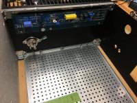
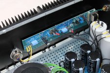
I was initially bummed out when I bought the chassis and then realized there was a deeper version that I didn’t buy. I went to 4U deluxe and clicked order. A drop box for the deep version would be handy. In any case I was going to drill an L bracket and mount the board, then put the SIT up high. Your picture made a light bulb go on. I did a 6-32 tap and test mounted a channel. Left and right will be swapped to mount upside down - no big deal.
I was initially bummed out when I bought the chassis and then realized there was a deeper version that I didn’t buy. I went to 4U deluxe and clicked order. A drop box for the deep version would be handy. In any case I was going to drill an L bracket and mount the board, then put the SIT up high. Your picture made a light bulb go on. I did a 6-32 tap and test mounted a channel. Left and right will be swapped to mount upside down - no big deal.
Attachments
I need a bit of help troubleshooting, please.
I got one channel all the way through...
.... Quote ZM - "if you're in ballpark of - say- 150-160mV and nice offset , put lid on and wait 10min , observing readouts all the time
coffee or tea are nice to have in proximity , and use it ........"
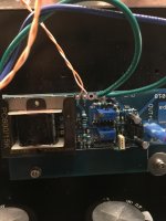
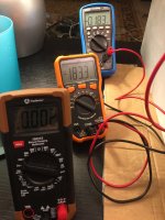
I powered off and connected the second channel. It is not behaving, and I cannot determine why. The initial offset and voltage seem fine. However, when I go to increase the Iq, the voltage does not increase per the norm. The voltage stays the same at 9.1mV or so, but the offset increases steadily and more rapidly than the norm with each turn of P1.
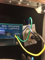
Here are a few pictures of the board in question. Any help is greatly appreciated.
I got one channel all the way through...
.... Quote ZM - "if you're in ballpark of - say- 150-160mV and nice offset , put lid on and wait 10min , observing readouts all the time
coffee or tea are nice to have in proximity , and use it ........"
I powered off and connected the second channel. It is not behaving, and I cannot determine why. The initial offset and voltage seem fine. However, when I go to increase the Iq, the voltage does not increase per the norm. The voltage stays the same at 9.1mV or so, but the offset increases steadily and more rapidly than the norm with each turn of P1.
Here are a few pictures of the board in question. Any help is greatly appreciated.
Attachments
...... The voltage stays the same at 9.1mV or so, but the offset increases steadily and more rapidly than the norm with each turn of P1.
Here are a few pictures of the board in question. Any help is greatly appreciated.
try fiddling with in same time with DC Offset trimpot ; can't see properly wires on SIT , so check did you wired it properly ..... need to tell that just in case
also confirm that you have proper 5V at output of 7805 reg
Perhaps a dumb question... is it necessary to use goop/grease with the insulation pad for the tokin sit?
if so called silicon pad - no goop
if mica , then goop
cal , there is a massive first post in thread
be sure that you understand each and every line ........ or mistake can cost dearly
0R1/3W - temporary put in neg rail , so you can place mV meter across and measure Iq, while setting the amp initially
you can use for same purpose R in CRC PSU filter , if you have it
Thanks ZM. Life's been stressful and apparently my brain is filling in a lot of information. I must have known that last night, but already forgot it today. Had already decided not to powerup today and wait for tomorrow, so fortunately I didn't do anything (additionally) damaging.
Thanks for the picture Cal! You made my life much easier!
I was initially bummed out when I bought the chassis and then realized there was a deeper version that I didn’t buy. I went to 4U deluxe and clicked order. A drop box for the deep version would be handy. In any case I was going to drill an L bracket and mount the board, then put the SIT up high. Your picture made a light bulb go on. I did a 6-32 tap and test mounted a channel. Left and right will be swapped to mount upside down - no big deal.
Glad I could do something to help. Good to give since I've been taking so much.
Poor ZM... Send out a bunch of boards and then get a ton of tech support requests while everyone builds.
Thanks for everything you do.
I need a bit of help troubleshooting, please.
I got one channel all the way through...
.... Quote ZM - "if you're in ballpark of - say- 150-160mV and nice offset , put lid on and wait 10min , observing readouts all the time
coffee or tea are nice to have in proximity , and use it ........"
I powered off and connected the second channel. It is not behaving, and I cannot determine why. The initial offset and voltage seem fine. However, when I go to increase the Iq, the voltage does not increase per the norm. The voltage stays the same at 9.1mV or so, but the offset increases steadily and more rapidly than the norm with each turn of P1.
Here are a few pictures of the board in question. Any help is greatly appreciated.
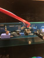
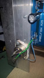
Looks to me like you've got your SIT connections backwards... I copied the wiring from ZM's image below. Center pin to the inside-most connection, ground to the middle, flying resistor to the outside connection:
Attachments
Thanks for the picture Cal! You made my life much easier!
I was initially bummed out when I bought the chassis and then realized there was a deeper version that I didn’t buy. I went to 4U deluxe and clicked order. A drop box for the deep version would be handy. In any case I was going to drill an L bracket and mount the board, then put the SIT up high. Your picture made a light bulb go on. I did a 6-32 tap and test mounted a channel. Left and right will be swapped to mount upside down - no big deal.
Also, your version looks prettier, but no tapping at all required if you put the boards and SIT in the position I did. They've got an extra hole in the center and that puts the SIT at the perfect distance to go into another pre-existing tap.
Looks to me like you've got your SIT connections backwards... I copied the wiring from ZM's image below. Center pin to the inside-most connection, ground to the middle, flying resistor to the outside connection:
I think you nailed it. I just got home, and I'm beat. I'll fix in the morning. Thank you!


I tried to be so careful and look at the schematic. I did not notice that the left and right were opposite. I looked at the little "line" on the board. Hopefully I did not damage anything...
Edited to add... Left and right are wired differently, correct? Just triple confirming. Right set up perfectly... but I want to be super-sure.
Continue to live and learn!
Last edited:
I think you nailed it. I just got home, and I'm beat. I'll fix in the morning. Thank you!
I tried to be so careful and look at the schematic. I did not notice that the left and right were opposite. I looked at the little "line" on the board. Hopefully I did not damage anything...
Edited to add... Left and right are wired differently, correct? Just triple confirming. Right set up perfectly... but I want to be super-sure.
Continue to live and learn!
Yep. You can see the other channel in Zen's build for Miko in the SissySIT thread: SissySIT (photo lifted from there and attached below)
Attachments
Last edited:
........... can't see properly wires on SIT , so check did you wired it properly ..... need to tell that just in case
.....
I need a bit of help troubleshooting, ......
........can't see properly wires on SIT , so check did you wired it properly ..... need to tell that just in case ......
wrote that this night , Today, 04:23 AM ........ forgot to power on that anti-mosquito thingie and had few harassing me , so I woke up ...... had a look at Greedy Boyz space ...... pretty much logical that I didn't saw clearly first pic - definitely miss-wired SIT
One more clarification before power-up given my trimpot issues... For P1, it should read 0 ohms between pins 2 & 3, correct (not between pins 2 & 1... Which should read 2k).
Thanks.
And I should have pointed out that it was ZM who identified the SIT miswiring earlier, I just gave the picture...
Thanks.
And I should have pointed out that it was ZM who identified the SIT miswiring earlier, I just gave the picture...
ZM and @Cal3713 - ......
We're cooking
hope that cooked meal will make us all green
one thing - even if I would always stay immensely thrilled with Edcor 600:15K value of sound vs. price ( ridiculous!) , optional Cinemags are few spears above , speaking strictly about sound and ignoring price difference
well worth changing them ...... not just my impression - our dear 'Talian friend expressed the same , somewhere on start of the thread (or maybe in some other Sissy thread , there are zillion of them
 )
)ZM - Thanks so much for the information. I had some of the Edcors left from my M2x build, so I used those. Also, with my noobishness, they looked easier to install...hope that cooked meal will make us all green
one thing - even if I would always stay immensely thrilled with Edcor 600:15K value of sound vs. price ( ridiculous!) , optional Cinemags are few spears above , speaking strictly about sound and ignoring price difference
well worth changing them ...... not just my impression - our dear 'Talian friend expressed the same , somewhere on start of the thread (or maybe in some other Sissy thread , there are zillion of them
Once I listen for a bit, get my wiring cleaned up, and try it with and without the BW cathode follower - I may be up for some desoldering and trying the Cinemags. I saw a lot of discussion re: core material that I did not understand. As a noob, I go simple. I get a working amp, and THEN I try to break it with upgrades
The dual mono was fun, but that was a big change for me.Note - me being impatient and not wanting to wait for the delivery time of the Cinemags maaaaay have also been a factor.
One more clarification before power-up given my trimpot issues... For P1, it should read 0 ohms between pins 2 & 3, correct (not between pins 2 & 1... Which should read 2k).
Thanks.
And I should have pointed out that it was ZM who identified the SIT miswiring earlier, I just gave the picture...
Sorry, missed a question mark in here: For P1, it should read 0 ohms between pins 2 & 3, correct?
- Home
- Amplifiers
- Pass Labs
- Babelfish M25, SissySIT - general building tips and tricks