

+1Start looking for nos irf244 or replacements.
it may cost as much as the amp itself

Those boards look pretty bad. You need matched devices and maybe boards. Are you in the US? We fix anything we have every made at a price nobody can beat especially if you smile. Current repair back log is zero.
that's the Man
")
certainly best solution
Service Manual are neither published nor issued
a direct request to passlabs provided the following reply from Mr. Kent English (from technical support):
For liability reasons we only can share service and build documents with authorized service centers, where you are physically located, so that I can refer you to the nearest known facility.
Extreme care needs to be taken with that amplifier, as matched output devices should they become damaged are difficult to source and quite costly.
What could be the reason for the D-G-S-shorts in the MOSFET's and the burnt gate-stopper resistors ?I’m not sure is this the right place for this. I bought a known broken X250. Right channel is out. I’d like to fix it myself. How hard of a repair? Where to get parts? Story in pics below.
View attachment 702748
View attachment 702749
Maybe too high idle current ?
I have measure between 45-50mV at each 0R47/3W source-resistor (i. e. ~ 90-100mA) (S/N 11651).
What is the correct value and which range of variation between the individual MOSFET's can still be accepted ?
I am confused about an additional thing on a power amp device, which I have for repair:
N-ch power mosfet are all IRF244 (not IRF240)
P-ch power mosfet are all IRF9240.
Was this the genuine condition or have the MOSFETs already been replaced ?
Thank you very much for an information.
Offset between +out and -out was 200mV and between each output and GND 1200mV.
After re-adjust (after warm-up phase of 2 hours and temperature of around 50 degrees) I observe around 3mV between the outputs and 5-8mV between all outputs and GND without significant drift.
At rear view (from the back panel) at the left channel on sub-board for front end left variable resistor is for lowest possible offset between the speaker outputs "+" and "-".
Variable resistor on right side for lowest possible offset between pos. and neg. speaker output and GND.
With the right channel the whole thing is reversed because the sub-board for front-end is inserted rotated by 180 degrees.
Last edited:
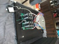
X250: Stripdown, Clean, Recapping and Schematic creating
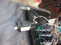
First image: Unusual Main switch: Single Pole White Toggle Circuit Breaker. Supplier:
A-Series White Toggle Circuit Breaker - Single Pole10A - Blue Sea Systems
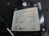
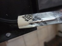
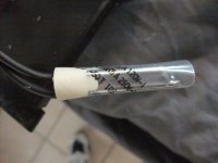
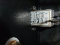
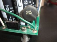
Second-third Image: ATC Semitec PEPI Thermostat
PEPI Thermostats and Thermal Protectors | ATC Semitec
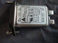
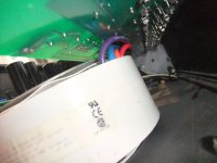
Fourth-fifth image: mains power entry connector (plug) with Emi/Rfi filter IEC 320/60320-C14 (IEC Inlet Filter)
Delta Electronics Manufacturer Part Number 10DEEG3B
Access Denied
https://www.mouser.de/datasheet/2/632/GE-515687.pdf
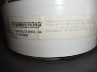
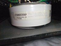
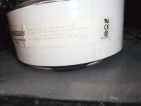
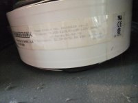
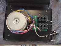
from sixth Image: Toroidal transformer POWERTRONICS AA-06624 rev. D, 2x32V5AC, 15A, LK0037
Transformers - Powertronix
First image: Unusual Main switch: Single Pole White Toggle Circuit Breaker. Supplier:
A-Series White Toggle Circuit Breaker - Single Pole10A - Blue Sea Systems
Second-third Image: ATC Semitec PEPI Thermostat
PEPI Thermostats and Thermal Protectors | ATC Semitec
Fourth-fifth image: mains power entry connector (plug) with Emi/Rfi filter IEC 320/60320-C14 (IEC Inlet Filter)
Delta Electronics Manufacturer Part Number 10DEEG3B
Access Denied
https://www.mouser.de/datasheet/2/632/GE-515687.pdf
from sixth Image: Toroidal transformer POWERTRONICS AA-06624 rev. D, 2x32V5AC, 15A, LK0037
Transformers - Powertronix
Attachments
-
 Airpax Carlingswitch.jpg979.8 KB · Views: 633
 -
 DSCF6584.jpg978.2 KB · Views: 618
 -
 DSCF6585.jpg993.8 KB · Views: 600
 -
 DSCF6602.jpg895.3 KB · Views: 604
 -
 DSCF6569.jpg983.2 KB · Views: 619
 -
 DSCF6574.jpg867 KB · Views: 233
 -
 DSCF6575.jpg994.9 KB · Views: 245
 -
 DSCF6576.jpg984.3 KB · Views: 170
 -
 DSCF6577.jpg986.2 KB · Views: 202
 -
 DSCF6579.jpg990.6 KB · Views: 212
Last edited:
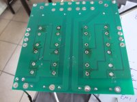
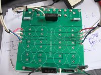
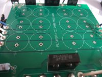
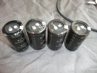
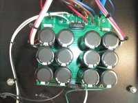
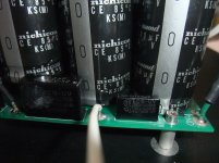
power supply PCB recapping
Attachments
-
 DSCF6597.jpg988.9 KB · Views: 303
 -
 DSCF6598.jpg1,007.8 KB · Views: 301
 -
 DSCF6599.jpg1,008.5 KB · Views: 288
 -
 DSCF6600.jpg1,008.5 KB · Views: 270
 -
 DSCF6608.jpg977.7 KB · Views: 251
 -
 DSCF6609.jpg877.8 KB · Views: 221
 -
 DSCF6610.jpg867.8 KB · Views: 226
 -
 DSCF6603.jpg1,016.1 KB · Views: 266
 -
 DSCF6601.jpg1 MB · Views: 250
 -
 DSCF6614.jpg998.6 KB · Views: 277
- Home
- Amplifiers
- Pass Labs
- Pass X250 repair