I think when the output current of the mirror is significantly larger
than the input current you probably want to think of it as a gain stage.
The question of why one might switch to having a second stage in the
front end has a simple answer in my case - I wanted to use the Toshiba
2SK170 / 2SK74 Jfets for the inputs instead of the existing power Mosfet
parts. The folded cascode or current mirrors require current from the input
pairs as large as the output current which has to drive the capacitance of
the output stage.
10 mA bias simply didn't cut it, and I wasn't ready to parallel large
quantities of those parts. In hindsight, it was a good decision...

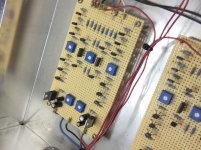
Here an example with current mirror in practical perfection
My UGS UP Amplifier
UGS Power : it's U.P.
2A & DIY
according the second image with schematic in post #1 from first URL the push-pull driver stage for the MOSFET power followers operates with slightly less than 30mA, but thus heatsinks are necessary.
Last edited:
removing of mechanical hum due dc on the mains - check out post #184 on page 19 under
https://www.diyaudio.com/forums/pow...zzing-toroid-transformers-19.html#post6455036
https://www.diyaudio.com/forums/pow...zzing-toroid-transformers-19.html#post6455036
on page 14 under
https://www.passlabs.com/wp-content/uploads/2020/05/xa100_om.pdfI read this:
The power supply of the XA 200 uses elaborate RF filtering and noise suppression designed to block AC noise and line DC. The substantial toroidal power transformer is followed by high speed rectifiers, and significant uF of computer grade capacitors in a passive filter arrangement. In addition to a main power switch the amplifier has a standby mode, which shuts down the bias to the circuit while keeping the supply active, significantly extending the life of the filter capacitors.
I. e., probably the approach according
https://linearaudio.net/article-detail/2242was realized.
On the X250 was only realized the the usual thing you know:
only a 50/60Hz bridge rectifier between transformer and power capacitors.
Are there any experiences concerning adding a snubber network and replacing the rectifiers by ultra fast versions like in use on XA200 ?
If yes, I would know, what diodes and what values for the CRC snubber network are in use.
According a XA100.5 clone under
https://www.behringer-electric.de/lautsprecher-service/pass-labs-diy/passlabs-xa100-5-mk2-diy/there is in use 4x MUR3020WT and a RC network consist of a wima 100nF/630V (MKP4) and a resistor 120 or 220R.
Maybe this will lead to a further sound improvement.
Thank you very much for an advice.
Last edited:
concerning matching of jFETs I want to know several details - go to
https://www.diyaudio.com/community/...k170-2sj74-2sk389-2sj109.413422/#post-7698859
https://www.diyaudio.com/community/...k170-2sj74-2sk389-2sj109.413422/#post-7698859