Hi Zen Mod,
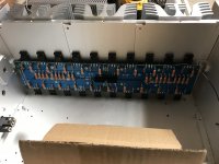
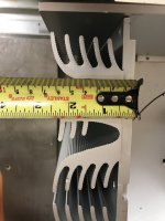
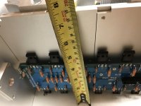
Today I finished assembling the Mosfets on the OPS PCBs and I decided to go in the garage to see how I would fit them in the chassis, only to realize that the chassis might be way too small for the thermal of this amplifier...
Here's a few pictures, please tell me your honest thoughts... Dimensions are as follow :
Internal measurements :
188mm Height
413mm Dept
255mm Width


If you tell me there's no chance I can make this work, could you send me a link to a proper chassis?
Thanks
Do
Today I finished assembling the Mosfets on the OPS PCBs and I decided to go in the garage to see how I would fit them in the chassis, only to realize that the chassis might be way too small for the thermal of this amplifier...
Here's a few pictures, please tell me your honest thoughts... Dimensions are as follow :
Internal measurements :
188mm Height
413mm Dept
255mm Width


If you tell me there's no chance I can make this work, could you send me a link to a proper chassis?
Thanks
Do
If the chassis configuration does not work as is, I have an idea that might just work... Take the heatsinks and put them in the middle to make like a wind tunnel and finish the sides with expensive looking wood. This way I could 3x Noctua fans under the chassis pushing or pulling air through the heatsink tunnel. This should give it way enough cooling.
My only problem would be the PSU sharing... Putting the PSU on one side would require extreme long cables for the other side and it would not be good... So, I'm thinking of having a dedicated PSU per side but connected to a single AC rectifying scheme feeding the two PCBs. Would this work? Or what about using two SLB PSU (from XRK971) per mono-block? I'm just worried that sharing a single pair of primaries on two bridge rectifiers would cause issues (humming noise, seen this before..).
Thoughts?
Thanks
Do
another thing - it's always good first to clamp/bolt mosfets to heatsink , then solder to pcb - simply because rotation of part is inevitable while tightening , even if you have it fixed with adjustable spanner , as you can see on pictures in my blog
however , as you already soldered them to pcb , you must re-flow all pins after heatsinking ..... to relieve mechanical stress from pins
however , as you already soldered them to pcb , you must re-flow all pins after heatsinking ..... to relieve mechanical stress from pins
So just to be on the safe side and double check everything...
OPS :
U-1, U-2, U-3, U-4 : PSU Negative supply (all tied together)
U+1, U+2, U+3, U+4 : PSU Positive supply (all tied together)
W1, 'W1, W2, 'W2 : PSU 0V (all tied together)
SA, 'SA, SB, 'SB : Speaker output (all tied together)
Thanks
Do
OPS :
U-1, U-2, U-3, U-4 : PSU Negative supply (all tied together)
U+1, U+2, U+3, U+4 : PSU Positive supply (all tied together)
W1, 'W1, W2, 'W2 : PSU 0V (all tied together)
SA, 'SA, SB, 'SB : Speaker output (all tied together)
Thanks
Do
another thing - it's always good first to clamp/bolt mosfets to heatsink , then solder to pcb - simply because rotation of part is inevitable while tightening , even if you have it fixed with adjustable spanner , as you can see on pictures in my blog
however , as you already soldered them to pcb , you must re-flow all pins after heatsinking ..... to relieve mechanical stress from pins
Aint that the truth, but he has so many parts to navigate, and they're already mounted. What's wrong with tapping well-selected holes for M4 between every other fet to fasten a beefy piece of aluminum bar or small u-channel stock to press clamp all those parts against the sinks? They'll slide under, then tighten.. Allows a little slop factor, and maybe even structural too. It's an idea!
Hi ZM,
I see the BZX90 is a 6.5V zener but a temperature compensated zener. You told me I could forget about those in the OPS, not populate or 9.1V zeners would be ok since there are already some in the IPS, correct? If I put in the 9.1V zeners on the OPS, do they have to be temperature compensated type?
The 7.5V zeners on the IPS, do they have to be temperature compensated type (OTC)?
I'm asking because this type of zener goes for about 10$ a piece!
But if it is what I need then it is what it is! hehe
Thanks
Do
you certainly read from Eagle generated BOM ( if I remember OK that I sent you that) that these are temp. compensated ones ........ in any case - use plain simple zenners , do not worry .... and now you know why I'm always saying that BOMs are baaaad for brain
my general rule is to avoid parts made of preputium wherever and whenever I can ....... we decided to use JFets here and there , SIT here and there , special voltage references here and there , but you'll never catch ZM - using fancyschmancy part , if there is proper industrial quality cheap one
in any case - good that you asked
I received your e-mail , btw.
We don't have those here but I did find this one, which seems to be hyperfast and soft recovery 60A... Not bad at all...
VS-UFH60BA65 Vishay Semiconductor Diodes Division | Discrete Semiconductor Products | DigiKey
VS-UFH60BA65 Vishay Semiconductor Diodes Division | Discrete Semiconductor Products | DigiKey
- Home
- Amplifiers
- Pass Labs
- Babelfish XJ , or JX …….. or whatever (Aleph X servo for Greedy Boyz)