That cap is there to shunt RF to ground if i've understood correctly, which will lower noise. I don't think the value is critical, but i used 100 nF iirc.
The live and neutral refer to the voltage carrying wires of your AC inlet. Per code, these should be color coded, though the color can vary depending on location. Blue is usually neutral, live is often brown or black (at least where i come from). Most IEC inlets will also have L, N and G or safety earth indicated on the pins, so you can go by that. What happens after the switch is less important, as the transformer does not have specific indications for L and N.
The live and neutral refer to the voltage carrying wires of your AC inlet. Per code, these should be color coded, though the color can vary depending on location. Blue is usually neutral, live is often brown or black (at least where i come from). Most IEC inlets will also have L, N and G or safety earth indicated on the pins, so you can go by that. What happens after the switch is less important, as the transformer does not have specific indications for L and N.
The live and neutral refer to the voltage carrying wires of your AC inlet. Per code, these should be color coded, though the color can vary depending on location. Blue is usually neutral, live is often brown or black (at least where i come from). Most IEC inlets will also have L, N and G or safety earth indicated on the pins, so you can go by that. What happens after the switch is less important, as the transformer does not have specific indications for L and N.
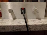
OK, I am comfortable with that aspect. However, I'm not sure how one could "switch" the live lead. To me this reads as "change the live lead from one to the other". Does it actually mean where to apply the "switch" that you will be installing? The switch is built into the Inlet, along with a fuse holder. The switch has 4 connection points which are above the main unit and fuse. Here is the spec sheet:
https://www.mouser.com/datasheet/2/358/typ_6765-1275662.pdf
This is the only aspect of this build that doesn't make any sense to me and seeing as it's the power and therefore a safety risk, I don't want to mess it up.
Look at the back of the IEC outlet. Pins should be labeled L N and G (or E, or a ground symbol). L = load/live pin, N = neutral, G = earth/safety ground. Connect the switch between the L pin and the transformer. The fuse should be between the switch and IEC outlet.
In the US the load/live wire is black, the neutral wire is white and the ground wire is usually green or green with a yellow stripe.
In the US the load/live wire is black, the neutral wire is white and the ground wire is usually green or green with a yellow stripe.
Last edited:
Look at the back of the IEC outlet. Pins should be labeled L N and G (or E, or a ground symbol). L = load/live pin, N = neutral, G = earth/safety ground. Connect the switch between the L pin and the transformer. The fuse should be between the switch and IEC outlet.
In the US the load/live wire is black, the neutral wire is white and the ground wire is usually green or green with a yellow stripe.
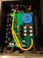
OK I think I got it now. What was messing me up was how we were singling out the Live lead and fuses, whereas this IEC Inlet is a bipolar switch, therefore both will be wired and fused through the Switch through their own terminals. I had some additional outside help clarify with me visually and double-checked continuity with a multi-meter.
Thanks to you, and silasmellor, for the help and explaining everything. Tomorrow I will try to finish wiring everything and test the supply. 🙂
Yes, by switching he means apply the switch on the live line. In your case, both leads are switched, which is even better. Simply run the leads from the inlet pins to the corresponding pins on top in the switch part and run leads from the other pair of pins on top to your transformer.
Yes, by switching he means apply the switch on the live line. In your case, both leads are switched, which is even better. Simply run the leads from the inlet pins to the corresponding pins on top in the switch part and run leads from the other pair of pins on top to your transformer.
Thank you for the confirmation and the help with the capacitor. I also had someone help me visualize it a little while ago and I understand it all a fair bit better. Now I just have to wire the power supply tomorrow so I can test, then find an appropriate capacitor.
My replies are a little delayed because a mod needs to approve them.
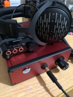
Beautiful! What is the switch on the left? Input selector?
AC switch. Same one you used in the BA-3 preamp build.
WHAMMY BOM
...
(4) RESQ R17 R27 R35 R26 47.5 ohm 71-RN55D-F-47.5
...
I don't know if this has been mentioned, but it should be R36, not R26. Confused me momentarily when I was laying things out and crosschecking between the schematic and the BOM.
Thanks again for providing this thread and these instructions. 🙂
Thanks for yet another incredible guide 6L6!!!
Does someone have info on the size of the PCB? The info is not readily available in the store... being a DIY, I was expecting to find that info at the very top of the product page, but, alas... there is no info! 😱 🙄 😱
I'm kind of planning my path and deciding what to tackle next: a new AMP like the M2x or AlephJ, or... if perhaps the path moves me more into the direction of buying a good pair of audiophile grade headphones and build the Whammy. My family will certainly appreciate this second path more! 🙂 As would my late-night listening sessions.
The interesting part here is that I could use most of the leftovers I have from my ACA chassis to make this one, as the heat dissipation is probably much less of a problem.
Thanks for any info! Best regards,
Rafa.
ps. Jason, one cannot miss the 'tease' back in August about the complete Kit. What does 'complete kit' mean? Full with chassis? Boards and parts? Parts and transformer? Thanks!
WHAMMY pcb size
The WHAMMY PCB is 160mm wide by 220mm deep. Fits in the Hammond 1455 series extruded enclosure.
The WHAMMY PCB is 160mm wide by 220mm deep. Fits in the Hammond 1455 series extruded enclosure.
Thanks! Yeah, makes a lot of sense. Watching the pics, the fit is really 'exact', so yeah, the Hammond dimensions are a perfect 'give away'. Thanks for the info!
Best regards,
Rafa.
Best regards,
Rafa.
Questions on building WHAMMY as preamp
My apologies if some of my questions have been answered before, I searched and scanned the thread for answers, but it is quite long now and didn't find the same questions.
I'm at the stage where I can stuff a circuit board, follow wiring diagrams and solder stuff ok, but I really don't understand the funciton of the circuitry beyond a very general sense and don't know any electrical engineering or circuitry design. As analogy, I'm a guy who could bolt a turbo charger to a car engine, but wouldn't be able to engineer and manufacture the turbocharger.
I am planning to build a WHAMMY to use as a pre-amp, with an amplifier similar to the original 20w Aleph. (Nirvana Electronics Works A-20). It will replace a Carver CT 7 preamp. Later I'd like to build an F4 to use with it.
I have a few questions:
1. Am I looking at the wrong project? Would a BA-3 preamp be better? From reading both build guides it looks like the WHAMMY is an easier and less expensive project and would work equally well. I think I could pull off the BA-3 but if there is little or no increase in sound quality, I'd prefer to save my money and time for the next project.
2. I'm wondering if the control switches and RCA inputs for 3, maybe 4 input sources can fit such a small chassis? Would it be a bad idea to crowd all of that into a small chassis? If i can still fit the WHAMMY into the Hammond chassis that would be a plus, smaller and cheaper is nice.
3. From the BA-3 preamp build guide thread, I notice that the volume control is a much different kind, is there an advantage to that type of volume control.
4. Would the type of selector switch used in the BA-3 preamp build work for the WHAMMY?
5. From the BA-3 build quide, it looks like the power switch would be wired between the AC input and the transformer. Therefore it needs to be capable of handling 120v household AC current. Can an illuminated switch be used, or is it better to use a separate LED as wired as outlined in this thread?
6. Any particular concerns for use as a preamp, Will I need the optional feedback compensation capacitor. Is a soft start/power up delay needed in a pre-amp?
7. I prefer headphone jacks that dont lock, is there any reason a stereo jack similar to a switchcraft guitar jack wouldn't work well?
Sorry for all these really basic questions, but reading through most of the thread has made me aware that there are many subtleties that aren't obvious to me.
Thanks, Jim
Hey Hook,
Im no expert, but here are a few replies to get you started, im sure some of the real experts will follw up.
1. Can't say, difficulty wise the Whammy is definitely easier since you don't have to deal with figuring out the PSU details or do any sort of setup (beyond checking voltages etc). I would wager that neither is better but they are different. With the BA-3 you have the option of adjusting the harmonic content, but that is probably more interesting once you've gotten a bit further into the hobby.
2. I built mine in a chassis from audiophonics (you can probably find similar on ebay in the US) that was a bit bigger and would fit things more comfortably. I think the Hammond chassis would be a tight fit, maybe too tight.
3. You can use either volume control with either preamp. Stepped attenuators are considered superior to traditional potentiometers (both in matching and long term reliability). That said, good old ALPS RK27 is still a good option for both that won't let you down. I used a valab stepped attenuator for my BA-3, a lot cheaper than the goldpoint used by 6L6, and there are several different ebay brands of stepped attenuators that have had good reports here.
4. Yes, as with the volume control, you can use them for either project with no problem. For selector switch, make sure you get the right number of tracks and decide whether you want to switch ground as well.
5. Yes, there are many types to chose from. You can get ones that use an LED for illumination that needs to be fed some DC voltage from your board. I think the ones that use AC for illumination will tend to flicker, which may be annoying, but someone else will have more experience with that.
6. The Whammy does give a pop in my headphones when powering on. You could use a soft start for sure, or simply switch the preamp on before the power amp.
7. Nope, those will work just fine.
Best,
Silas
This makes a fine pre-amp. Use any jacks and switches you want to. Power consumption is low so just leave it on and you will get no noise or thumps.
If built as shown it will work fine and you won't need the compensation caps.
If built as shown it will work fine and you won't need the compensation caps.
LM833 DC offset
Hi Budweiser,
I was surprised you got 0.1mV DC offset with an LM833 and 100K R3 and R5.
I get a no load DC offset of -0.1mV with 5.1K R3 and R5, and an OnSemi LM833N, and I get the following voltages on the opamp pins :
1 O/P1 -0.29
2 I/P 0.0
3 I/P 0.0
4 VEE -16.66
5 I/P 0.0
6 I/P 0.0
7 O/P2 -0.27
8 VCC 16.36
Could you kindly post the voltages you have on the pins of your LM833 ?
Finally completed this project. Just a note, I used the 100k standard in R3 and R5 with LM833 and Fairchild and came in at 0.1mV no load DC offset, good enough for me.
Hi Budweiser,
I was surprised you got 0.1mV DC offset with an LM833 and 100K R3 and R5.
I get a no load DC offset of -0.1mV with 5.1K R3 and R5, and an OnSemi LM833N, and I get the following voltages on the opamp pins :
1 O/P1 -0.29
2 I/P 0.0
3 I/P 0.0
4 VEE -16.66
5 I/P 0.0
6 I/P 0.0
7 O/P2 -0.27
8 VCC 16.36
Could you kindly post the voltages you have on the pins of your LM833 ?
Last edited:
- Home
- Amplifiers
- Pass Labs
- "WHAMMY" Pass DIY headphone amp guide