Hi 6L6, can I use IRFP240/9240 as output mosfet? And also does the output mosfet affect the sound a lot?
Thanks!
Not ideal.
IRF610/9610
IRF510/9510
This is probably ok too in a fully insulated package
IRFI620GPBF
IRFI9620GPBF
Another possible combo
IRFI614GPBF
IRFI9610GPBF
Last edited:
Oh thanks, I’m considering making my own pcb to work with my discrete opamp, and maybe dc servo if necessary.
Is IRFP240/9240 size is the problem or is it just not compatible?
Also does Darlington work? For example BC139/140 cascade with D44H11/D45H11 in darlington topology?
Is IRFP240/9240 size is the problem or is it just not compatible?
Also does Darlington work? For example BC139/140 cascade with D44H11/D45H11 in darlington topology?
Last edited:
OP on input IS working as DC servo circuit, at least when thinking of output offset
240/9240 - besides size ( issue for original pcb) , there is aslo issue of much higher intrinsic capacitances ...... you loose some, and not gaining anything, comparing to intended mosfets
as written already in WHAMMY related threads - you can throw anything in output - mosfets, bjts, darlington, IGBT ....... circuit is automatically biased
though - it's wise to conduct changes to some circuit only if you understand what you're changing and why ........ which I'm having impression is not the case, taking in account questions you made
It was the issue of shortage of component. I can’t find FQP and IRF610/9610 at local store, and I have a bunch of matched toshiba BJTs and some pair of IRFP240/9240. Ordering components at mouser is fine but shipping cost is insanely high to my country.
I’m a noob as you said but I gotta work with what I got.
I’m a noob as you said but I gotta work with what I got.
you really need xformer with lower voltage
problem with smaller xformers is that they're having so called "poor regulation factor" meaning that voltage difference between full load and light load is huge
they're usually made in a way to have rated voltage at full load
either that , or insert at least 51R/3W in each secondary leg going to diode bridge
I think you're right, I've just ordered the suggested 18V PTX...
70054K PC Mount Transformer 110/230V-18/36V 110V-36V 110V-18V 230V-18V 230V-36V
It's a shame because I somehow ended up with three of the 22V ones after only ordering one and was going to use them to build a couple of WHAMMYs for friends. Best to get it right though, I don't want to damage these Opamps.
Not sure why 6L6 recommends 22V + 22V. I used 18V + 18V and it works beautifully.
With the 18V PTX did you "make R16, R22, R29, R32 15ohm" as suggested in 6L6's original post?
Hi there!
I just started building my Whammy today! This is my first DIY amp project, but not my first electronics project.
The parts where ordered according to the BOM with exception for U2 (NJM7915FA), which i had to substitute for an L7915CP as I could not source the other part here in Europe. I followed the linked guide.
I had to stop at step 13 as the voltage on the negative rail between R13 and R14 was at around -26V instead of -17V. The voltage at the positive rail was exactly at 17V, D5 and D6 also lit up. I also did not notice any magic smoke after connecting to mains voltage.
I have the suspicion that U2 might be dead, but I have no idea why?

Does anyone have another idea what could be wrong here?
Thanks in advance!
I just started building my Whammy today!
This is my first DIY amp project, but not my first electronics project. The parts where ordered according to the BOM with exception for U2 (NJM7915FA), which i had to substitute for an L7915CP as I could not source the other part here in Europe. I followed the linked guide.
I had to stop at step 13 as the voltage on the negative rail between R13 and R14 was at around -26V instead of -17V. The voltage at the positive rail was exactly at 17V, D5 and D6 also lit up. I also did not notice any magic smoke after connecting to mains voltage.
I have the suspicion that U2 might be dead, but I have no idea why?
Does anyone have another idea what could be wrong here?
Thanks in advance!
JermNZ - The 22v will work just fine. You'll get about 26V before the regulators which is well below their max input value. You could, if you wanted, use bigger resistors in the CRCRC filter if you wanted, maybe 10R instead of 5.1R, but it's not required.
Use the transformers you have. I've built a number of these with 22V transformers and they work perfectly. 22V transformers were the kit standard for 100's of kits.
chrzr - Thank you for the photos. Nothing appears wrong. Is the 7915 soldered in properly? Aside from it being defective as you suspect, that's about the only thing I can imagine might be wrong...
JermNZ - The 22v will work just fine. You'll get about 26V before the regulators which is well below their max input value. You could, if you wanted, use bigger resistors in the CRCRC filter if you wanted, maybe 10R instead of 5.1R, but it's not required.
Use the transformers you have. I've built a number of these with 22V transformers and they work perfectly. 22V transformers were the kit standard for 100's of kits.
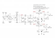
But I seem to be getting 31.5V before the regulators, does this mean something is a miss with my build?
Please see schematic with my measurements attached.
Attachments
Last edited:
36V? Is this under no load?
Your notes say 31.6V
Sorry made an error in my post, around 31.6V is correct (edited).
36V? Is this under no load?
Your notes say 31.6V
Measurements were taken with no input and the volume turned down to minimum.
36V? Is this under no load?
Your notes say 31.6V
Awesome.
Carry on.
So that's fine?
No need to worry about high temp of regulators or high voltage at regulator output?
Should I consider the naked reg config?
BTW, (and slightly OT...) this may, quite seriously, be the prettiest gainclone in the entire world -
Gainclone Integrated Amplifier – Jeremy Young Design
Gainclone Integrated Amplifier – Jeremy Young Design
Last edited:
JermNZ - The 22v will work just fine. You'll get about 26V before the regulators which is well below their max input value. You could, if you wanted, use bigger resistors in the CRCRC filter if you wanted, maybe 10R instead of 5.1R, but it's not required.
Use the transformers you have. I've built a number of these with 22V transformers and they work perfectly. 22V transformers were the kit standard for 100's of kits.
chrzr - Thank you for the photos. Nothing appears wrong. Is the 7915 soldered in properly? Aside from it being defective as you suspect, that's about the only thing I can imagine might be wrong...
Thanks for the quick reply!
So I have soldered in a new regulator and I still got -26V between R13 and R14.
I just compared the Datasheets of the L7915CP and the JRC part and I seem to have overlooked the input voltages when ordering
 ... RS probably just suggested the ST part based on the output voltage
 I've just ordered the correct part. Hope it arrives soon under the current circumstances
- Home
- Amplifiers
- Pass Labs
- "WHAMMY" Pass DIY headphone amp guide