I will be using K60 and J18 VFETs. Is it satisfactory to measure the Vgs using a Peak Atlas DCA75 or am I better to use the approach diagrammed by Mr. Pass?
Your all V-FET's have the same T-54 rank.
Imho Mr. Pass DUT diagram is more close to real work condition of the amplifier.
Make them hot for 15 minutes , temperature stabilise on the heatsink
then take Vgs measurements.
Sony VFET Amplifier Part 2
Greetings
Attachments
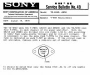
Sony VFET Amplifier Part 2
Sony VFET Amplifier Part 2
Sony VFET Amplifier Part 2
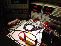
You can use two 19 Volts laptop psu's connected together for bipolar
(-) (0 Volts, center tap ) and (+).
Two bench lab psu's ( current limited 1A max ) are always great tools.
My setup on the pictures")
Sony VFET Amplifier Part 2
Sony VFET Amplifier Part 2
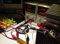
You can use two 19 Volts laptop psu's connected together for bipolar
(-) (0 Volts, center tap ) and (+).
Two bench lab psu's ( current limited 1A max ) are always great tools.
My setup on the pictures
Attachments
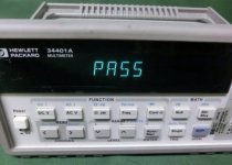
Pass
I appreciate your economy of language!
Correct.
Q1 n-jfet k170
Q2 p-jfet j74
NPN for Q3 and PNP for Q4, so
ZTX450 for Q3 and ZTX550 for Q4
I can also confirm that Q5 (left position when looking at the pcb) must be P channel, so either 2SJ313 or FQP3P20. Q6 (right position) must be N channel, so either 2SK2013 or FQP3N30.
RodeoDave thanks for this. I'm ready for the first stage of power up.
Just to double confirm, on the ZTX450/550, the round side is the side with the writing on it?
Ok, so I was able to confirm orientation from datasheets, where I should have gone in the first place!
I've powered up both boards, and with 510r in r34/35 I get around 4.7v across both r34/35 on both boards.
How do I ascertain Jfet idss from this and adjust r34/35?
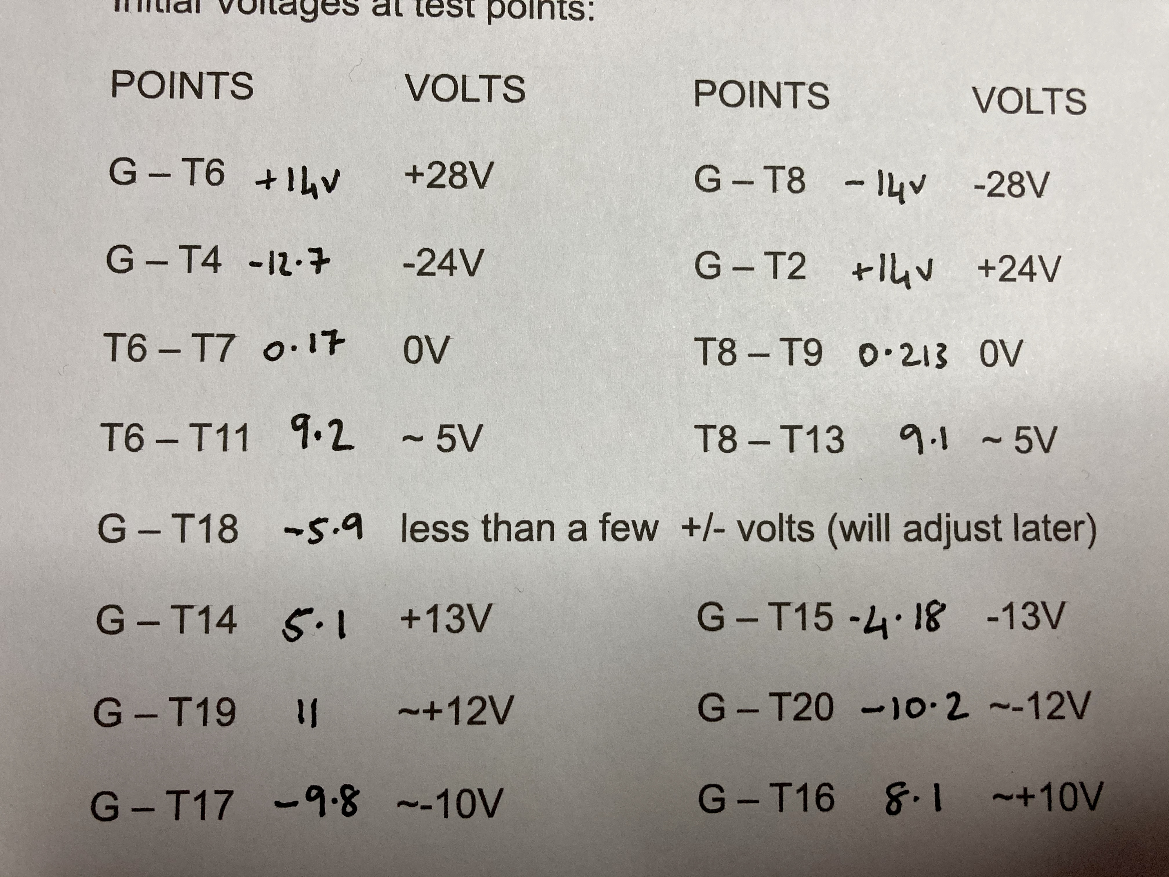
My voltages are way off from the initial voltages as noted by Nelson. I'm using the Fairchild JFets
I've powered up both boards, and with 510r in r34/35 I get around 4.7v across both r34/35 on both boards.
How do I ascertain Jfet idss from this and adjust r34/35?
My voltages are way off from the initial voltages as noted by Nelson. I'm using the Fairchild JFets
There are no source resistors on the jfets so there are running at Idss.
So the voltage drop across R34/R35 is just the Idss times the resistance.
So the current is 4.7V/510 ohm ~ 9.2mA
A lot of numbers are different because with 510R for R35/R34 your mosfets are
now on. (See T6-T7 and T8-T9 voltages).
But things like G-T6 and G-T8 shouldn't change since those are just the rail voltages.
G-T4 and G-T2 also shouldn't change.
Please check these, as well as your raw DC rail voltages.
Last edited:
- Home
- Amplifiers
- Pass Labs
- Sony vFET Illustrated build guide