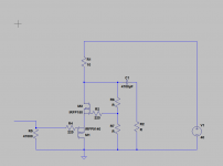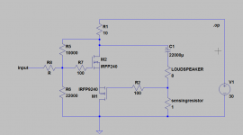
I had this idea this morning. I am about to start building some version of this.
This is just a very simplified schematic to show the general function.
This should be able to give the simple Zen-amp a respectable bass control (i hope), similar to what the positive current feedback does to the First Watt F7.
I am very tired this morning so please excuse any error i might have made.
I have only simulated this with DC, and it seems to work. I will test it further in LT spice soon.
Any thought or criticism on this idea?
Cheers,
Johannes
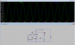
It seems to work in LT-Spice at least. I don't know how to simulate and calculate output impedance, distortion etc..
I will place a 100 ohm potentiometer parallel to the sensing resistor so I can adjust the amount of postive feedback and the output impedance of the amp on the fly. I am much more interested in listening to it play music then simulated performance (even though I am curious about the simulated performance to).
Green trace = output, blue trace = input.
That 10 ohm resistor is a simplified constant current source. It can (and should) be replaced with a real active constant current source or an Aleph current source.
There is a lot of possible improvements. This is just a very simple example to test the basic idea of positive current feedback in a very simple single stage amp inspired by Nelson Pass and his First Watt F7. When he writes about replacing 30 dB of negative voltage feedback with 2 or 3 dB of positive current feedback to have the same damping-factor, I got very interested.
Cheers,
Johannes
https://www.youtube.com/watch?v=I01DJOnCt1A
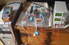
A terrible youtube video of a very simple and crude amp playing.
I am surprised that it will actually play music. It is a ratsnest build with salvaged parts.
The bottom p-chanel fet is an IRF9530 and the n-chanel part is an IRLB3813. A 30 volt, 230 watt part with to much transconductance and some "exciting" and strange looking curves.
I am running 320 mA quiescent current through the fets. I used two 47 ohm power resistors as a 23,5 ohm drainload.
I am listening to it at the moment and I have been playing the usual Pink Floyd, Sub6, Aretha Franklin Noir Desir through it. As long as I don't try to play loud it actually sounds almost pleasant.
The best thing with this amp is that no matter what I try to do with it I can not make it any worse....
Cheers,
Johannes
I have been playing with shorting out the one ohm sensing resistor while playing some music through the amp. Even with this simple crude setup I could clearly hear a very pronounced difference in general character. With positive feedback the amp becomes much more "alive" and energetic. Without the positive feedback (shorted sensing resistor) the amp becomes boring, dull, compressed and looses a little gain. The gain reduction is not very large. A guess a dB or so. But the amp suddenly sounds very dull. This positive current feedback is really something. It does breathe life into the otherwise very polite and overly well behaved amp.
I am longing for a well built amp with some better parts and less dangerous design.
A couple more watts output and an ampere or two more current could probably work wonders.
Cheers,
Johannes
I am longing for a well built amp with some better parts and less dangerous design.
A couple more watts output and an ampere or two more current could probably work wonders.
Cheers,
Johannes
My idea is to buffer the posititive feedback and to inject the feedback into the source of the gaindevice to get a very wideband, low distorsion phaselinear positive feedback loop. This enables more positive feedback with less distorsion before occilation. It should be stable with very little phaseshifts very far above any audio frequencies.
This circuit can be buffered with a class A or A/B outputstage (the same lateral devices as in the F7) to build a powerful amp with only one voltage gainstage. It does have a very high potential gain if loaded with a constant current source or a bootstrapped resistor drainload.
It should make a great input/voltagegain stage.
I want to explore simple single stage negative output impedance bass amps, and this is where I ended up.
Cheers,
Johannes
View attachment 535992
Any thought or criticism on this idea?
At the very least it shows a good imagination. I would pursue it if I
were you.
😎
Hi Johannes,
thanks for sharing this! I like your enthusiasm about this!
And, as I just read here yesterday: Time not spent with a experiment is wasted time! So keep on!
I think that Nelson showed us the positive feedback and it's role for using this as all the other working parts in all his amplifiers. So, as you do, take one thing (positive feedback from the F7) and implant this into another (Zen) and see if this works as expected. And as you suggest, you can of cause add a current source later, say an aleph one, or...
Happy progress and lots of fun!
Matthias
Edit:
And if also the master gives it encouraging blessings... 🙂
I got pretty good simulated results (.03%THD) out of this circuit with a UJN1208K SiC power JFET as the gain device and a 'standard' CCS, so it seems promising to me (although I am far from an authority).
Last edited:
I would pursue it if I were you.
Thanks for encouragement!! I wish I had your knowledge and deep understanding of the sometimes black magic art of amplifier development. I am just an amateur playing with an idea.
I hope more people will test this idea. I posted my idea here on the forum to share them.
Nothing beats some real collaborative development effort.
Today I am testing and experimenting with this very crude first test-amp.
I am surprised by the amount of power I can get from this simple circuit. I have 15,5 volts power supply and I run 320 mA through the amp. 23,5 ohms drainload power resistors and I can easily fill my living room with music. I does start to distort some when there is some deep prominent bass in the music though. I would have been surprised by 1/3 of this power and sound quality.
I got pretty good simulated results (.03%THD) out of this circuit
That is some pretty impressive simulated results. Thanks!
And if also the master gives it encouraging blessings...
Yes. His blessings is very encouraging.
I have been mulling over this circuit for the last two days...
I need to buy some low voltage high transconductance p channel parts. I want as low impedance under the gaindevice as possible.
Cheers,
Johannes
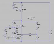
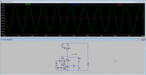
This is my latest update on this amp.
I have not fired it up yet... I am waiting for my soldering iron to become hot. I have one resistor left to solder.
Since I use mosfets that are not in the standard library of LT-spice, it is not perfectly correct.
M1 is an IRF9530.
M2 is an IRLB3813 and M3 is again an IRF9530.
Green trace is output. Blue trace is the positive feedback and the red trace is the signal in.
Cheers,
Johannes
With a 750 mA constant current source things got very interesting. I have never heard this clean and dynamic bass from my large BIB loudspeaker. Even my QSC RMX1450 sounds dull in comparison. The QSC has much more power of course, but within this small Zen amps available power it sounds much more controlled and more more dynamic and lively. The QSC sounds sterile. I have been playing Sub6 so my living room floor was shaking. This is not very hard to do with a large BIB loudspeaker and a high efficient 10 inch pro driver though.
I ran frequency sweeps from 10 Hz and it was very very clean. At some frequencies I could here some buzzing sounds from inside the large BIB, but I guess it is the cables rattling.
With a shorted sensing resistor (no positive feedback) it becomes dull and sounds hollow somehow. It is two very different amps with and without the positive feedback...
I hope someone else here wants to build and test something similar. I can really recomend playing with some positive current feedback, and especially with simple on or two stage class A amps.
Thanks Nelson Pass for your F7 article. It was an eye opener.
Cheers,
Johannes
Helllo Circlomanen. The lower IRFP9240 [M1] in the above schematic has an idle Vgd~zero V. Is it an amplifier? Maybe its drain need be at a voltage which is more negative than common; say -5 to -10 Vdc!
Last edited:
The lower IRFP9240 [M1] in the above schematic has an idle Vgd~zero V
Yes, but it has a Vds of -4,4 volts and will be linear down to about -1 volt drain-source.
This enables the bottom p-channel fet to swing 6,8 volts into the source of M2. The bottom P-channel fet is a buffer for the positive feedback. Usually the large Vgs of normal enhancing mode switchfets like the IRFP series is a drawback. Here it is a feature as it enables it to be dc coupled to the sensing fet. A logic level gate fet like the IRL series would not be as suitable as there would be much less available voltage swing without some kind of level shifting.
If you want to you can always bias the M1 fet with some kind of voltage source like a battery or some resistor dividing setup and couple the positive feedback through a capacitor to the gate of the M1 p-channel fet, but I see no need for the added complexity and increased parts count.
I think the use of the large Vgs of switchfets as a level shift is turning a disadvantage into an unexpected advantage.
It is all about turning the characteristics of the parts into synergistic effects to minimize parts count and maximize performance. Using the disadvantages in a new way so to mitigate their effect or even make them into advantages.
The bottom p-channel fet is a like one leg of a long tail pair, the other leg of the long tailed pair being the M2 gain device. The source of the p-channel M1 ties into the source of the main gain-device M2. M1 buffers the positive current feedback and drives it into the gain device from a very low impedance source.
If you short out the sensing resistor the M1 p-channel fet will act as a low impedance connection to ground. It is like a voltage regulator.
Cheers,
Johannes
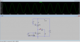
Here is only the bottom P-channel fet (M1) with a simple constant current source (M2).
There is a 6,8 volts 1000 Hz sinus tone being feed into the grounded gate of M1 and the resulting wave is shown as a trace. It is measured on the 8 ohm resistor (load).
You can see that the source of M1 is at 4,588 volts which is the Vds of the device.
Cheers,
Johannes
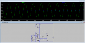
Here is a screenshot of the simulation.
The green trace is of course the output of the amp.
The blue trace is the positive feedback.
The positive feedback is only a small fraction of a Volt for an output of almost 6 volts.
The positive feedback loop has a huge margin of potential voltageswing.
Cheers,
Johannes
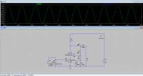
And here is a very simple and crude simulation of the last variation.
This amp will probably have more gain and much less distortion then a stock Zen amp (but it has two amplifying devices so no contest).
Common gate is the most linear and fastest way to use a mosfet, followed by common drain. This is a common drain device contributing only current gain driving a common gate which contributes only voltage gain.
R1 should be replaced by a constant current source, an Aleph current source, a transformer or a huge inductance with a low dcr
Green trace is output.
Blue trace is signal in.
Last edited:
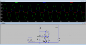
And this would be the PCF version of the amp in my last post.
It is just one more resistor and one capacitor to get some postive current feedback.
I prefer my first version. Fewer parts, and I believe it is much more important to keep the positive feedback loop so fast and linear as possible to enhance stability, so that is why I choose to feed the positive feedback into the bottom fet instead.
Red trace is positive feedback.
Blue trace is the signal in to the amp.
Cheers,
Johannes
- Home
- Amplifiers
- Pass Labs
- Positive Current Feedback simple Zen amp
