"Bias and DC offset are VERY interactive." Looks like you have 1 turn pots,with this amp you need 10 turn pots.
Papa used single turns, but I like the multi-turns myself. They are not too expensive.
Papa used single turns, but I like the multi-turns myself. They are not too expensive.
Yes,Papa probably knows exactly where to set the pots before powering up.
I found even with multi-turns the pots for adjusting bias and DC offset do affect each other quite a bit. Oreo, you helped me get the presets pretty close. 😉
I found even with multi-turns the pots for adjusting bias and DC offset do affect each other quite a bit. Oreo, you helped me get the presets pretty close. 😉
I fiddled with the resistance settings of the pots in LTspice (as individual resistors), then preset the pots to those approximate values. They came out pretty close, requiring only fine-tuning.
He is Papa
🙂
He probably just closed his eyes and adjusted the pots by touch and smell

Last edited:

I finally tried setting the "balance" pot by measuring the DC voltage between each input JFET pin 3 (source) and the output + terminal and matching the N and P devices in-circuit that way. Worked well and sounds good! Solid imaging. I also upped the bias to give me 55 deg C at the heat sink base plate on the sink side directly opposite each output device.
I'm using a BA2018 as a preamp. The combination provides musical detail I have not heard before. Not harsh. Now I have to go back and listen to all my favorite recordings all over again; nice work if you can get it 🙂
I'm using a BA2018 as a preamp. The combination provides musical detail I have not heard before. Not harsh. Now I have to go back and listen to all my favorite recordings all over again; nice work if you can get it 🙂
Hi Brian,
Could you add some details about the system for the board (plastic, Teflon, …?)with the "turrets/posts"? What are they and how are they fastened into the plastic layer?
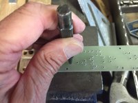
Holes are drilled in the G10 board with a #43 drill bit. Then I prefer to over drill them with a 3/32" drill bit to about a fourth of the way down from the top side. A bit of patience is required to get the drill press stop set correctly. You are then rewarded with a hole that allows easily placing the turret vertically in the board before pressing, without it falling over or going into the hole at an angle while pressing. Still leaves plenty of material for a solid press fit.
Pressing tool is a 1/4" machine bolt with the head cut off, and a 1/8" hole drilled in the end, sized to clear the top of the turret but not the shoulder. Tube depot has the plans. Used in a drill press without the motor running to press the turrets into the board holes. I use a block of wood with a 3 business card thick layer to absorb where the turrets poke slightly through the far side of the board.
Although pressed turrets in a #43 hole are tight enough to use without staking the bottoms, I prefer to stake the turrets with an old center punch reground to a wider angle. You also can grind another 1/4" bolt to do the job. I use a hammer with the punch although you have to be very gentle or the turrets can get bent. Alternatively, I have also used the drill press with the staking tool chucked in it to lightly flare the bottom of the turrets.
This board has a tighter layout than typically recommended. A pressing tool with a tapered end was used to allow the close spacing. Properly sized turret circles with cross hairs were added to the KiCad "user comments layer" of each device footprint and the PCB board layout printed with just that layer as a drilling template. The template was spray glued to the board and removed after drilling. Getting the holes exactly in the center of each of the crosshairs was the challenge!
Attachments
I do not think that $3000,- is too much Money also to consider that it made is the US and that you get 3 years of warranty.
Yeah, and we should be supporting local business as much as possible, now more than ever.
Finally got around to building an F7. Modeled the circuit in LTSpice to make sure it would work. Laid out a schematic and PCB in KiCad and used it to create a drilling template for some old-school G10/turret post boards. I bought some ECX10N20-S and ECX10P20-S lateral mosfets from Profusion in the UK and a matched quad set of LSK170/LSJ74 Jfets from the DIYaudio store. Built the boards to match the mounting layout in a M2x amp I had built.
It all went very well. Bias and DC offset are VERY interactive. Still playing with the Balance pot, trying to use my scope to set it up but thinking there may be a better way. Running about 0.12 volts drop across the 0.1 ohm resistor which yields a conservative 55 degrees C at the transistor body. Amp already sounds very good, very detailed, very different from my F6 as well as very different from my M2x. Well worth the effort so far. I'll try pushing the bias up a bit after I break it in some more. Balance seems to affect the imaging, so I can see that will be critical as well.
Many thanks to Papa for this fascinating PCF amplifier design!
looks cool!!! you are building it according to which schematics?😱😱

@avdesignguru, if you haven’t tried the F7 with your WHAMMY yet, you should. I found the BA2018 very detailed as well but the WHAMMY seems to smooth things out just enough without sacrificing detail, imaging, or stage.
looks cool!!! you are building it according to which schematics?😱😱
chchyong89:
You must do your own homework on this one. 😀
chchyong89:
You must do your own homework on this one. 😀
Ha Ha Ha! I will flip the google upside down tonight!🙄
chchyong89:
You must do your own homework on this one. 😀
Yes - if you read most of the 1500 replies in this thread you'll get the idea.

Yes - if you read most of the 1500 replies in this thread you'll get the idea.
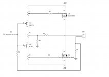
OK. I've attached the basic idea. Draw this up in the modeling program of your choice (I used LTSpice) and start plugging in appropriate resistor values until you get something that works.
Attachments
Thanks Brian for the detailed description and handy hints - very neat piece of P-P assembly.
Also the same for "wtnh" version too - it takes a lot of care to get that assembly tidy - mine often use "resistor // resistor", crossed wiring, isolation sleeves, etc (otherwise known as "chicken scratch"!) I sometimes think this old way of assembly actually sounds better for some circuits.
The old vero board with just the holes and copper donuts isn't around anymore these days - loved that stuff!
OK. I've attached the basic idea. Draw this up in the modeling program of your choice (I used LTSpice) and start plugging in appropriate resistor values until you get something that works.
Coool~~~😀.
Member
Joined 2009
Paid Member
... the one I would REALLY love to build (for keeps). I am willing to lay down my soldering iron after that. 😀
so says the DIY addict down through the ages... "sure, I can quit any time, just this last one project..." 😀
Last edited:
- Home
- Amplifiers
- Pass Labs
- First Watt F7 review