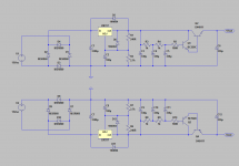
R1, R2 are just simulation artefacts.
They are not on the Vero board layout.
R1 represents output impedance of the signal source.
Especially for amplifiers with bipolar transistor inputs, it will show up potential issues with the base current.
So no need to include one physically.
R2 is useful to make sure the input is not floating in case there is no input connected.
I normally solder a SMD 100k resistor across the input connections.
You can also use a normal resistor across the RCA input socket.
Patrick
Cool....that makes sense. I've lots to learn about simulation. 🙂
I had not included R1 in my build as it wasn't on your board and Nelson explained R2 in his F5 Manual.
Should have my other channel ready to test this weekend.....looking forward to a complete working amp.
I had not included R1 in my build as it wasn't on your board and Nelson explained R2 in his F5 Manual.
Should have my other channel ready to test this weekend.....looking forward to a complete working amp.
Test them with a 50R resistor load and adjust the offset after 30 minutes warm up.
.... before you connect your headphones.
If you do get oscillations with 2 channels, or some sort of hum, add a 2R power resistor between each amplifier rail connection and the cap multiplier output.
So total 4 resistor. The exact value you need to do trail & error.
Then try the local caps at the amp (after those 2R resistors) and see if you hear any difference.
Always better to use separate supplies. 🙂
Patrick
Test them with a 50R resistor load and adjust the offset after 30 minutes warm up.
.... before you connect your headphones.
If you do get oscillations with 2 channels, or some sort of hum, add a 2R power resistor between each amplifier rail connection and the cap multiplier output.
So total 4 resistor. The exact value you need to do trail & error.
Then try the local caps at the amp (after those 2R resistors) and see if you hear any difference.
Always better to use separate supplies. 🙂
Patrick
Good idea about 50R for testing. My phones are nominally 32 ohm so I may try close to that. And don't worry....I'll use some el-crapo headphones until I'm confident about function and stability. 🙂
Yes, it occurred to me that a low value power resistor in the supply would help isolate them....so it is good that you have suggested a value for me to start with. Thanks!
Yes, agreed about separate supplies. I'm hopping that if my listening tests are encouraging, then I'll make a fresh build.....with better matched output FET, neater layout and separate supplies (and perhaps with your boards.... if you still intend on doing this and sharing them here 😀 )
And thanks Patrick for your encouragement and help....very much appreciated.
(now I'd better get back to work before boss spots me!)
Well, at least two people here have reported positive subjective experience with the circuit topology. 🙂
Don't wait for my boards, you don't need to.
Just get your current 2 channels to work with separate supplies.
And then enjoy them.
It will be months before I can get them done, and then, as usual, I shall not make them public till I have tested.
So we'll be looking at end of 2015.
And if you still like the amp then, you can always consider a new build.
You may send me a email via the forum to get a copy of the preliminary Bill of Materials.
Patrick
Another teaser.
My current layout using a ebay / taobao "2107" heatsink enclosure :
Aluminum chassis case enclosure amplifier chassis headphone box 212*70*257 mm | eBay
😉
Patrick
.
My current layout using a ebay / taobao "2107" heatsink enclosure :
Aluminum chassis case enclosure amplifier chassis headphone box 212*70*257 mm | eBay
😉
Patrick
.
Attachments
Looks sweet Patrick.
I got the other channel up and running yesterday...no probs.
However the little 20VA tranny proved not up to the task and with L & R connected there was too much sag in the rails for proper running and evaluation. So I'll guess I'll knock up a more substantial supply....possibly follow your recommendation in posts #59 & #60 ....with two separate supplies.
Another question Patrick, you increased the gate stoppers to 1k which has certainly prevented stability issues.....but what is the downside to higher values of stoppers aside from possible attenuation of input signal. Increased noise perhaps?
> but what is the downside to higher values of stoppers
Reduced bandwidth, but you are still over 1MHz anyhow.
I would not hesitate to go as far as 2k.
> aside from possible attenuation of input signal.
Will not happen.
> Increased noise perhaps?
All the resistors used in this circuit are quite low in value, compared to say an Aleph-H,
or any opamp based headphone amps, for that matter.
20VA will only do for 1 channel.
So time to go dual supply.
Patrick
Thanks Patrick. Of course that makes sense re bandwidth.
I'll actually rip out the supply from my existing Tortello's 'zen-like' headphone amp and put in the proto F5 boards and a couple of fresh PS. Could take a while but I'll report back once done.
I'll actually rip out the supply from my existing Tortello's 'zen-like' headphone amp and put in the proto F5 boards and a couple of fresh PS. Could take a while but I'll report back once done.
> I'll actually rip out the supply from my existing Tortello's 'zen-like' headphone amp ....
That's just a normal LM317/337 PSU, not ?
If I am not wrong they cannot take low ESR caps at the output.
Patrick
That's just a normal LM317/337 PSU, not ?
If I am not wrong they cannot take low ESR caps at the output.
Patrick
Would a feedback network like in the original F5 work if paralleled output devices were used, say two IRF610 and two IRF9610 in parallel per channel?
If each device has its own source resistor - why not?
Values of source resistors should be increased (e.g. 1E) and bases of current limiters should have 1k resistors to every source resistor.
Values of source resistors should be increased (e.g. 1E) and bases of current limiters should have 1k resistors to every source resistor.
> Would a feedback network like in the original F5 work if paralleled output devices were used, say two IRF610 and two IRF9610 in parallel per channel?
Let's suppose you wish to use the original F5 feedback network with a 22R resistor between Gnd and the source of EACH JFET.
And let's further assume that you want a close loop gain of 6.
The feedback resistors will then be 2x 110R.
The output, even without any headphone connected, will then see 66R to Gnd.
Assuming further that you have a 32R headphone, the total load at the output is then 22R.
At full voltage swing (say 20V pk-pk), we are looking at peak output current of 470mA.
Of course you can parallel and then bias the MOSFETs to 250mA total.
Whatever gain in bandwidth you might have in using such a configuration, you loose in return in your open loop response.
So apart from wasting energy, I don't see the point of doing so.
The only motivation I can see is that you can use a standard F5 PCB without any changes.
If that is the sole reason, then you should perhaps consider using the schematics in post #25.
Patrick
> I'll actually rip out the supply from my existing Tortello's 'zen-like' headphone amp ....
That's just a normal LM317/337 PSU, not ?
If I am not wrong they cannot take low ESR caps at the output.
Patrick
By 'rip out' I meant remove and put aside. What I'll be doing is building a new pair of PS as you suggested, and putting them into the existing case together with the F5 HA boards and a couple of toroids.....I have confidence that the results will be acceptable (and hopefully wonderful 🙂 ) The case already has power cord,fuse, pot, sockets etc and this will also make it easier to smuggle back into the lounge room past the missus for proper long term evaluation.
Yes, the existing PS presently in the case use Tangent’s TREAD boards using stock LM317AT etc..
Bear in mind what I said about low ESR caps with 317/337.
You may wish to consider placing a cap multiplier as I described before between 317/337 and F5HA.
1) It will lower the output noise of the 317/337 substantially. You hear more details against a darker background.
2) It will provide high bandwidth power to the F5HA.
3) It will also isolate the 317/337 from the load at those high frequencies, when the 317/337 becomes inductive.
Patrick
Bear in mind what I said about low ESR caps with 317/337.
You may wish to consider placing a cap multiplier as I described before between 317/337 and F5HA.
Will do.....ie per post #60. That was exactly my plan! 🙂
You can do post #60.
But it will dissipate double the power because of the shunt leg.
So you need 30VA transformer per channel, plus double the heat sink (about 12W per channel).
On top of that there is no reduction in noise of the 317/337.
(But still worth trying).
The one I referred to in #135 is something like the attached.
Patrick
.
Attachments
Thanks yet again for your advice Patrick. It is wonderful how freely you share your depth of knowledge, and your enthusiasm. Very much appreciated.
The idea came from John Curl.
This is the PSU for line stages in one of his Parasound products.
I just exploited his idea for headphone amp applications.
Patrick
This is the PSU for line stages in one of his Parasound products.
I just exploited his idea for headphone amp applications.
Patrick
Hi,
I plan to use similar PSU for headphone amp.
My plan is using CRC filter before 317/337 for additional ripple filtering, and use K multiplier (Keantoken) instead of C multiplier, performance (from his page):
Input rejection: +66db/-54db or +2k/-500
Output impedance:
112mR at 25mA
45mR at 50mA
27mR at 100mA
20mR at 200mA
17mR at 400mA
Excess output inductance (in inches of wire): at or below 1.
Output current: 1.4A max continuous. 20-400mA max for linear operation.
Output voltage: Limited to the Vcemax of Q1, but see Other Adaptations for a version for any voltage.
Voltage drop: ~1.8V (can be less but this gives good operation)
Max input ripple before saturation: 1.5V pk-pk (0.46Vrms on an AC multimeter)
I'll do it with 2 PCBs, first RAW DC CRC finished and second (317/337 => K-multiplier) in works.
Probably overkill but why not 🙂.
First PCB additionally have transformer secondary "Hagerman" snubbers & rectifier diode snubbers (R+C or C only).
- Home
- Amplifiers
- Pass Labs
- F5 Headamp ?