Why is it so difficult to download LTSpice (for free) ?
Patrick
.
Is this power supply needed to connect with heat sink ? . ( regarding the post # 85 )
Last edited:
Try to learn to calculate dissipation (= voltage drop x current).
Then study the datasheets of the devices.
And decide for yourself whether heat sink is necessary.
(It takes more of my time to type all these than to give you a simple yes or no.)
Patrick
Then study the datasheets of the devices.
And decide for yourself whether heat sink is necessary.
(It takes more of my time to type all these than to give you a simple yes or no.)
Patrick
If a quick hamburger for 1 USD is what you are looking for,
you will be much happier at MacDonald's than at a Michelin 3-Star.
Patrick
you will be much happier at MacDonald's than at a Michelin 3-Star.
Patrick
Hi friends,
I just discovered the thread. Just for the record: I'm using this http://www.diyaudio.com/forums/headphone-systems/208751-kind-f5-my-head.html amp, since three years and I'm still happy with it.
It does not have to "shy away" from comparisons with other (even very expensive) amplifiers.
It's even a decent preamp if you need the gain. And yes I'm sure it will drive F4. ;-)
I highly recommend building a headphone amp based on F5 topology.
Best regards
Floric
The problem of using the original F5 power amp feedback network as you did lies in that the value of R7, R8 (at JFET source) cannot be much higher than 10R, or else you would end up with too much degeneration and too low bias for the first stage.
Once the value for R7,R8 is chosen, the values of the feedback resistors R17, R18 will determine closed loop gain.
However, in case a low closed loop gain is desired (say 5x), the corresponding values of the feedback resistors are too low.
And they end up loading the output excessively (25R for 5x CL gain).
This is why I went back to the ProFET type simple feedback network.
The feedback shunt resistor no longer degenerates the JFETs and thus one can choose the value with much more freedom.
But Stixx seemed to agree with you on the good sound.
http://www.diyaudio.com/forums/pass-labs/271926-f5-headamp-2.html#post4311067
Patrick
Incidentally, IMHO it is easier to reduce loop gain (for closed loop stability) by increasing the value of the MOSFET source resistors.
In my case I am using 3.3R, compared to your 0.5R.
In case of Wayne's MOSFET source follower for the PASS DIY Headamp, he is even using 10R.
http://www.diyaudio.com/forums/pass-labs/271662-new-passdiy-headphone-amp-coming-soon.html
Patrick
In my case I am using 3.3R, compared to your 0.5R.
In case of Wayne's MOSFET source follower for the PASS DIY Headamp, he is even using 10R.
http://www.diyaudio.com/forums/pass-labs/271662-new-passdiy-headphone-amp-coming-soon.html
Patrick
Hi Patrick,
thanks for the quick reply. When I built my amp, I had the idea of increasing the MOSFET source resistors too.
But to be honest, I forgot why I didn't choose this route. It's three years ago and I didn't make any notes...
Best regards
Floric
thanks for the quick reply. When I built my amp, I had the idea of increasing the MOSFET source resistors too.
But to be honest, I forgot why I didn't choose this route. It's three years ago and I didn't make any notes...
Best regards
Floric
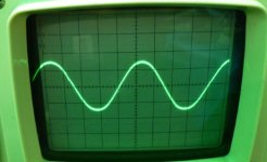
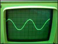
Finally got time on Sat morning to get one channel up. Looking good. Bandwidth exceeded my micky-mouse function generator's 140KHz limit. Mothers day here today so I'll have to wait until next week to put the second channel together. Then temp box it up and sneak it past the 'trouble and strife' into the lounge room for some listening sessions.
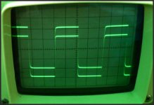
First 2 scope shots are input trace ontop of output trace 10 KHz and 100 KHz (see what I mean about my toy function generator). Not quite square trace is 10 KHz. Input below output. The gain is a bit under 5x.
I left out the local filter electros for the time being. Seems OK. I also replaced the 100 ohm jfet gate resistors with 1k as suggested by Patrick.
Attachments

Last edited:
Well, we'll see how well the PS copes with double the load once I get the other channel up and running.
Yes, no hickups.......but I spent much more time checking my circuit than building it. 🙂
I've found that spending time triple checking is always quicker than troubleshooting a blown up one after I've let all the smoke out.
Yes, no hickups.......but I spent much more time checking my circuit than building it. 🙂
I've found that spending time triple checking is always quicker than troubleshooting a blown up one after I've let all the smoke out.
The load would be the least of the problem for your cap multiplier.
If anything, you will probably get more problems from two high speed circuit sharing the same supply interacting with each other.
(i.e. potential oscillations)
I am actually quite amazed that you did not get any already, despite the long distance between the last cap and the F5-HA.
But we'll soon find out, I guess. 🙂
And yes, very wise to spend time checking rather than just power up blindly and hope for the best.
Patrick
I am actually quite amazed that you did not get any already, despite the long distance between the last cap and the F5-HA.
But we'll soon find out, I guess. 🙂
Patrick
I will be cutting down the board width when complete and so I’ll make sure the PS is closer, leads twisted etc. Perhaps I’ll put in the local caps as you have.
In very rough terms, what sort of freq range would I be looking at for oscillation? What sort of voltage swing? (I’ve never built anything with this sort of bandwidth before) My scope is just an old CRT 35MHz jobbie.
A few MHz, full voltage swing.
You will not miss.
And add things one at a time (local cap, 2nd channel, .....
Else you have no idea what causes the instability.
Patrick
You will not miss.
And add things one at a time (local cap, 2nd channel, .....
Else you have no idea what causes the instability.
Patrick
Last edited:
I was asked by PM about my statement earlier in post #109 :
"The problem of using the original F5 power amp feedback network as you did lies in that the value of R7, R8 (at JFET source) cannot be much higher than 10R, or else you would end up with too much degeneration and too low bias for the first stage."
To demonstrate the effect, I have attached both the original version, and a modified version with the original F5 feedback network, but using (deliberately) a 100R degeneration resistor. When you run the Spice files, take note of the current Id through the 2 JFETs. Also note that I had to increase the JFET drain resistors by more than 3x to get back the same bias current on the 2nd stage.
And I am quite sure it will not take long before you figure out why the first stage bias (Id of Q1, Q2) has dropped.
The feedback network used by Floric is somewhat a mixture of the two.
(R6, R7, R12, R16, R17, according to his schematics)
Patrick
Attachments
Last edited:
- Home
- Amplifiers
- Pass Labs
- F5 Headamp ?