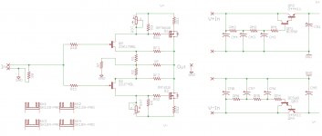
It is essentially a normal Cap Multiplier using a CFP as pass device.
Examples of something similar could be found at the JLH Class A site some 14 years ago.
http://sound-au.com/tcaas/jlhcapmult.htm
For this particular application, I have consciously decided against using a CFP as pass device, in favour of normal Darlington.
Firstly the circuit has relatively good PSRR according to my simulations.
And there is no noticeable increase in distortion as a result of a few ohm of power supply impedance.
But it demands a high-frequency-stable power supply to prevent oscillation.
And it is well known that CFP in certain applications can become unstable at HF due to the local feedback within the CFP.
No such problem with the Darlington.
But don't let me discourage you.
Try it and let us know.
Just bear in mind and not be surprised if it oscillates.
Stixx found out the hard way. 🙂
Patrick
Last edited:
Out of curiosity, I simulated the JLH BJT circuit posted in post #5, which is of the "same" topology as the F5-HA.
I used the numbering according to Circuit 2 here :
The Class-A Amplifier Site - JLH Headphone Amplifiers
Devices were changed to modern day versions for the simulation.
I used 2SC2240/2SA970 for the frontend, and 2SC4793/2SA1837 for the power stage.
At least the latter are still available widely (e.g. Mouser). And the former are also not yet unobtainium.
Of course you can also use the more generic BC550/560 and BD139/140.
Q3, Q4 are for bias control, but as already discussed in Hesener's F5 Stax Amp, they are not entirely free from AC signal.
At least in the simulation, the version with bias control has noticeably higher distortion.
Nevertheless, for those who like the simplicity and do not want to FETs, this is not a bad performer.
Patrick
.
Attachments
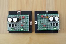
Patricks proto F5 has been playing music for a while now with several simple psu's to try... now I am planning to eventually case it up with a permament supply.
For that I have built a bipolar supply of Nazar regs, both working trouble free and outputting around +-15V (they are within 1,5% of each other).
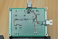
The sharp eye will notice that they are not 100% mirror identical, but good enough for now. Filtering is CRC with 4700uF-3R3-4700uF. SMD parts are underneath.
Now need to get a custom made 2 x 18V transformer (actually don't need to but want to 🙂 )
For that I have built a bipolar supply of Nazar regs, both working trouble free and outputting around +-15V (they are within 1,5% of each other).
The sharp eye will notice that they are not 100% mirror identical, but good enough for now. Filtering is CRC with 4700uF-3R3-4700uF. SMD parts are underneath.
Now need to get a custom made 2 x 18V transformer (actually don't need to but want to 🙂 )
Attachments
Very pretty P2P build.
How much total bias (300mA) per supply ?
To be true to the Nazar, you need to remove the 1000µF Panasonic at the F5-HA, and replace by 0,33µF WIMA MKP2.
But then you might want to try as is first, and change as the final step before putting in the case.
Also remove the tantalum and replace by WIMA MKS2, same value.
🙂
Patrick
The regs were built according to your schematic ( 🙂 )... this is why the 22uF for the Adjust bypass is a tantalum.
MKS2 only goes to 10uF to my knowledge. Big enough?
MKS2 only goes to 10uF to my knowledge. Big enough?
Ah, that one ......
I have horrible experiences with tantalum, including failure with a total short.
So for that position I would have used a electrolytic.
The larger the better, can go even to 47µF or 100µF 25V, whatever fits.
Then parallel by a Panasonic PPS 100n 50V (SMD 1210) on the back side of the PCB.
You can get them from Reichelt.
The spice file I posted has 240mA total current for the Nazar.
If you bias the F5-HA to 150mA, then the 2.7R wants to be lowered to 2.2R or 2R.
Nazar needs to have 2x current of the F5-HA.
That is the penalty of a shunt power supply circuit.
Patrick
Last edited:
Thank you for the quick reply.
Will exchange for a 'lytic (should have something close in the drawers) and a PPS (might even have some of those...).
Will also change the 2.7R to a lower value.
What is a possible benefit of running the F5A somewhat hotter (lowering the 3.3R bias on the F5 board or increasing supply voltage?
Will exchange for a 'lytic (should have something close in the drawers) and a PPS (might even have some of those...).
Will also change the 2.7R to a lower value.
What is a possible benefit of running the F5A somewhat hotter (lowering the 3.3R bias on the F5 board or increasing supply voltage?
Stixx, are you going to try both the P.S. suggested by EUVL (Nazar and "JC style" cap multiplier) and report? It might be very interesting...
P.S. If interested, I designed simple single layer pcbs for both solutions, F5HA+Nazar and F5HA+Cap multiplier, that can be etched at home.
P.S. If interested, I designed simple single layer pcbs for both solutions, F5HA+Nazar and F5HA+Cap multiplier, that can be etched at home.
> If interested, I designed simple single layer pcbs for both solution: F5HA + Nazar and F5HA+ Cap multiplier
Looks like I have competition.
Except that I have one PCB for all published variants. 🙂
> are you going to try both the P.S. suggested by EUVL (Nazar and "JC style" cap multiplier) and report?
Maybe you should try (DIY) yourself, since you already have the PCB done ??
Patrick
Looks like I have competition.
Except that I have one PCB for all published variants. 🙂
> are you going to try both the P.S. suggested by EUVL (Nazar and "JC style" cap multiplier) and report?
Maybe you should try (DIY) yourself, since you already have the PCB done ??
Patrick
Last edited:
> What is a possible benefit of running the F5A somewhat hotter (lowering the 3.3R bias on the F5 board or increasing supply voltage?
Increasing bias and voltage will almost always reduce distortion.
That does not necessarily mean hotter, because temperature depends also on the heat sink size.
And you do not necessarily have to change the 3R3 in order to increase bias.
So where is the limit, before it becomes a F5 power amp ?
Sticking to the same devices, I would say +/-20V 600mA bias.
It will drive even a 16R load with 20V pk-pk to very low distortion.
The voltage is limited by the JFETs, and the bias by the Rthjc of the MOSFETs.
(Assuming max heat sink temperature of 55°C)
Possible down side ? Thermal drift.
And I assume you know how to size the power supply accordingly.
Still not enough ?
It is then easier to go to a cascoded F5 power amp.
🙂
Patrick
.
Attachments
It can be the same temperature if you increase the size of the heat sink by 5x.
For the version posted in #150, and assuming you don't use a shunt regulators, theF5X power amp case would just be sufficient. 😉
If you were to use shunt regulators, then you would be looking at one of those largest cases from HF2000.
Or use water cooling.
Patrick
For the version posted in #150, and assuming you don't use a shunt regulators, theF5X power amp case would just be sufficient. 😉
If you were to use shunt regulators, then you would be looking at one of those largest cases from HF2000.
Or use water cooling.
Patrick
Last edited:
Oh yes! When you're so kind to share interesting ideas, somebody might follows 😉Looks like I have competition.
Except that I have one PCB for all published variants. 🙂
One "universal" pcb demands daughter boards and big pcbs not so easy to be etched at home. My goal is to have 2 complete ch in just one "eurocard" 16 x 10cm. This can be done with the Cap Multi solution, while the Nazar, due to the heat managment, requires more heatsink and splitted pcbs (raw ps and regs+F5HA)
Just designed, not etched (so far).Maybe you should try (DIY) yourself, since you already have the PCB done ??
The real reason is I have no time (and too much €€€) to make both, thus I asked if somebody else was going to test them and report
I like shunt p.s. very much, but the cap multipler solution looks intriguing if you mind the polar bears 😉
I already have a suitable case (not big enough for the more complex Nazar) and a pair of 15+15V trafos, that means the more expensive parts.
As I mentioned before, the cap multiplier has lower noise and lower dissipation.
So if I have to choose one, this will be what I choose.
It is not difficut to change from one to the other.
They use esentially the same components.
Patrick
So if I have to choose one, this will be what I choose.
It is not difficut to change from one to the other.
They use esentially the same components.
Patrick
While I can squeeze two 15+15V/20VA trafos, two 8 x 9 cm pcbs and one pot in a HiFi2000 Galaxy 23 x 28 x 4 cm I own, for the shunt version I have to buy a Galaxy Maggiorato of the same size (at least).
Not to mention the two new 18+18V/30VA trafos...
I'll follow your suggestion and go for the cap multi 😉
Not to mention the two new 18+18V/30VA trafos...
I'll follow your suggestion and go for the cap multi 😉
> for the shunt version I have to buy a Galaxy Maggiorato of the same size .....
You need side heatinks for sure for the shunt version.
Patrick
You need side heatinks for sure for the shunt version.
Patrick
P.S. If interested, I designed simple single layer pcbs for both solutions, F5HA+Nazar and F5HA+Cap multiplier, that can be etched at home.
Thank you Massimo for asking, but I see no need on my side. I have the F5 and Nazar boards already P2P, and I will build the
cap multiplier as well which can be squeezed on an even smaller board.
F5 boards go on the heatsinks on each side of my planned case that will be plenty big, also to support the demands of either psu.
I hate vero hacking, so...
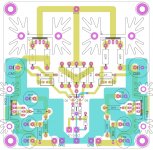
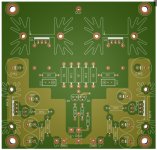
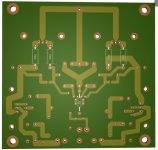
Dimensions 10x10 cm.
Darlington Cap mutiplier added on board. Power comes from Raw DC CRC board.
This heatsink is 6.5 K/W, cca 20 deg up, cca 3W per FET, 200mA*15V?
Patrick, please be gentle in comments 🙂joker: just joking, fire from all cannons)
Dimensions 10x10 cm.
Darlington Cap mutiplier added on board. Power comes from Raw DC CRC board.
This heatsink is 6.5 K/W, cca 20 deg up, cca 3W per FET, 200mA*15V?
Patrick, please be gentle in comments 🙂joker: just joking, fire from all cannons)
Attachments
Last edited:
- Home
- Amplifiers
- Pass Labs
- F5 Headamp ?