Try the one in post #60 for your final build.
The spice file posted has the right values for 150mA bias.
Patrick
The spice file posted has the right values for 150mA bias.
Patrick
Hi Patrick,
I very much appreciate you posting the spice files and making it
easy to play with the designs.
Cheers,
Dennis
I very much appreciate you posting the spice files and making it
easy to play with the designs.
Cheers,
Dennis
> I very much appreciate you posting the spice files and making it easy to play with the designs.
Pleasure.
In addition to playing with Spice, you should also study the datasheets thoroughly.
For example, it tells you that if you use a low ESR cap such as mylar for C7 in post #85, you are likely to get oscillations.
Spice helps you to understand parameters and components in circuits.
It is still not all reality.
In the end you have to build something.
And then measure, then listen.
Patrick
Patrick thanks I had not seen that before and its a great read.
If you wish to have low even harmonics
Speaking of low even harmonics... in fact the F5 HA is sounding very very clean with a quality of treble
I have not heard before in my system. Detailed yet almost lush; gentle when it's called for but also very
dynamic when you have a suitable recording.
The F5 has an easiness to it that makes for very long listening sessions... it just reproduces the music in
a natural way... from the very bottom to the top 😉
Time to build a final psu and to case it up.
As you can tell my prototype is now with Stixx.
He has quite a few other headamps and at least 2 top of the range phones.
So I think he is the right candidate to make a neutral (well it is always subjective) evaluation.
For the prototype I used 2SK170BL / 2SJ74BL which are Idss matched to 10µA.
The MOSFETs I used were IRF510 / IRF9510.
For the 20+ each that I had, there were no matched N-P pairs.
So I just used NN-PP match as close as possible.
The IRF510 has about 4V Vgs at bias, the IRF9510 about 4.2V.
Since I have not measured 100's of them, I cannot tell for sure whether they will have overlapping Vgs.
The penalty is a bit more even harmonics.
But it didn't seem to matter, if you trust Stixx's judgements.
You do want the left and right channels to be as identical as possible though.
At least I do.
Patrick
Thanks , i am planing to use separate power supply . what is the specification of transformer ? .
Note that this is for a cap multiplier or 7815/7915 type regulators, and 150mA bias.
You will need 35VA 2x18Vac for the Nazar reg because of extra voltage drop across R7 & R3, in case of +/-15V rails and 150mA bias.
Alternatively, 30VA 2x15Vac would be sufficient for +/-12V rails. You need to change R2 & R5 accordingly to lower the voltage.
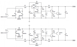
Also I discovered a small typo in post #81. Sorry for that.
The values are for a bias of 120mA, and total current draw is 240mA.
For 150mA bias (300mA total current), change R3/R6 to 2R.
Patrick
You will need 35VA 2x18Vac for the Nazar reg because of extra voltage drop across R7 & R3, in case of +/-15V rails and 150mA bias.
Alternatively, 30VA 2x15Vac would be sufficient for +/-12V rails. You need to change R2 & R5 accordingly to lower the voltage.
Also I discovered a small typo in post #81. Sorry for that.
The values are for a bias of 120mA, and total current draw is 240mA.
For 150mA bias (300mA total current), change R3/R6 to 2R.
Patrick
Last edited:
Clever stuff, though I personally always rewire to use separate Ground wires.
http://www.diyaudio.com/forums/head...ne-amplifier-vfet-s-f-buffer.html#post4312906
😉
Patrick
http://www.diyaudio.com/forums/head...ne-amplifier-vfet-s-f-buffer.html#post4312906
😉
Patrick
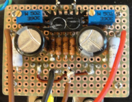
What value are the 2 electrolytic caps on your boards pictured below?
I assume they are for power supply filtering?
I didn't see them shown in the schematic from post 5.
From your other photo they appear to be 25V Panasonic FR-series caps.
Thanks...
I assume they are for power supply filtering?
I didn't see them shown in the schematic from post 5.
From your other photo they appear to be 25V Panasonic FR-series caps.
Thanks...
Attachments
Last edited:
- Home
- Amplifiers
- Pass Labs
- F5 Headamp ?