OK, so I'm going to select a few quotes from the QA400 thread that specifically deal with my F5T build. Those that are relevant to the measurement or use of the QA400 will be left in place.
---------------
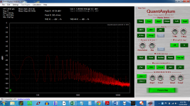
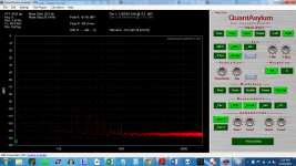
OK,so I got this MARVELOUS shot by holding an 8" metal file wrapped in stranded 18 awg hookup wire connected between two alligator clips while in loopback mode.
Same at the back where the speaker posts are... I assume that at the rear, it is radiating from the unshielded power cord. I will borrow a shielded one and see if that helps.
This seriously looks like diode switching and harmonics from MUR3020 diodes.
Would snubbing work? Should I just follow Quasimido's rules? (Mark Johnson's bell ringing snubber).
---------------
OK,so I got this MARVELOUS shot by holding an 8" metal file wrapped in stranded 18 awg hookup wire connected between two alligator clips while in loopback mode.
Same at the back where the speaker posts are... I assume that at the rear, it is radiating from the unshielded power cord. I will borrow a shielded one and see if that helps.
This seriously looks like diode switching and harmonics from MUR3020 diodes.
Would snubbing work? Should I just follow Quasimido's rules? (Mark Johnson's bell ringing snubber).
Attachments
Last edited:
1audio said:Simpler-
A coil of wire (with or without the file) from BNC hot to BNC shield. Connect to the QA400 input. Turn off the source side of the QA400 and start a continuous measurement. You should see 60 Hz and it will go up when you move the coul near an active power transformer for example. if the transformer has a rectified load you will see a lot of 120 Hz and harmonics. If loaded with an incandescent light bulb or a resistive heater it will be mostly 60 Hz.
These are ideal for this: Item # EP-101A, AC Probe-Axial-20 mV On Magnetic Shield Corporation and do pop up on ebay for lots less than $70.
__________________
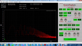
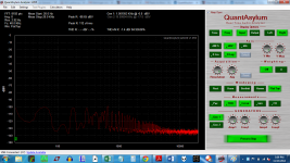
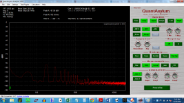
OK four shots with that method, around an 8" file.
First is at the diode bridge at the front of the amp
Second is at the power cord at the back of the amp
Third is across the room at my workbench.
Fourth is in an enamelled steel can
There is no difference when the QA400 is placed in this can.
First is at the diode bridge at the front of the amp
Second is at the power cord at the back of the amp
Third is across the room at my workbench.
Fourth is in an enamelled steel can
There is no difference when the QA400 is placed in this can.
Attachments
1audio said:Time to look at the wiring around the transformer, bridge and caps. They should all be tightly twisted pairs minimizing the loop area so the radiation is minimized. There is a lot of harmonic energy around the rectifier. The LF falls off but the harmonics radiate further which may make sense.
Follow each current as a loop. Go from where it originates, e.g. power cord line to switch to fuse to transformer to power cord neutral. The area inside that loop need to be as close to zero as possible even if you need more wire to make it work. Transformer secondaries to rectifier to caps. Keep the centertap close to the other two wires or you have a 1/2 wave loop on each cycle.
__________________
Demian Martin
Product Design Services
It's all tightly twisted except that the center tap is independent of the other two voltages.
I am going to try to reduce the loop areas, but I am using a bunch of relays for the slow-charge circuit. So the wiring may not be as tight as would otherwise be expected.
I hope the issue is just at the diode bridge, though I may have to rewire that a bit. The center tap wiring heads straight for the cap bank, while the diode bridge is off to the side of the amp.
All of these circuits were mounted on the faceplate of the amp. Maybe they ought to be reorganized more sensibly? I will check through it with the coil of wire tomorrow, with the top off.
THANK YOU FOR YOUR HELP!
The replacement scope is on the way, so I will be able to snubberize the transformer.
1audio said:Wind the centertap with the leads from the transformer and on to the caps. Every 1/2 cycle the current goes through 1 diode, lead from the transformer and one lead to the caps, next 1/2 cycle through the alternate lead. Always returning through the centertap.
Its a common mistake since it seems that there would be no current through the centertap but there always is. You can take the current clamp from the QA190 and clamp that around the leads and see what is happening. Use the waveform view on the QA400 to see the waveform. It will not be pretty.
OK, so I need to make a braid.
I wired the secondaries to a barrier strip so that I could feed a single pair of wires to the rectifier, instead of two pairs... you see my transformer has 5 Center tapped secondaries. I connect the secondaries at the barrier strip prior to going to the rectifier, and leave one set of CTapped secondaries unused.
I was trying to use this boat anchor of a transformer for something.....Please don't tell me I will need to buy more iron!
re are a couple of "before" shots, looking for problem areas, with about 20 turns of wire wrapped around a metal file, then the file is taped from end to end with electrical tape, in case I drop it.
The first shot is with the sensor away from the DUT. Note how low the magnetic field tester is reading.... this is "ambient".
The second is under the amp, at the left channel barrier strip... I have included a barrier strip between the secondaries and the slow charge circuit ( which lives on the faceplate of the amp, along with the rectifiers and cap banks.). The intent is to be able to easily remove the toroid in the event that the amp needs repairs.
The third is under the barrier strip that connects right channel secondaries to the rectifier.
From here, the secondary wiring goes to two diode bridges, one per channel.
Visual inspection shows that the right channel twisting of the secondaries to the barrier strip is not as tight as the left.
Also, since the circuit path is Toroid -> barrier strip -> rectifier ->blocking relay -> thermistor || bypass relay -> cap bank, I think I can replace the barrier strip with the blocking relay, thus losing quit a bit of open loop area.
The circuit would then go:
Toroid -> blocking Relay -> rectifier -> thermistor || bypass relay -> cap bank.
This will take some work....
THANKS!
Perhaps it is best to simply move the toroid and main power supply away from the amp?
["bear" said:the slow start relay, if that is what it is, is best positioned in the primary, not the secondary.
I'm unclear on what a blocking relay is. I presume the bypass relay parallels the thermistor?
Again I prefer to put all the soft start stuff in the primary.
Perhaps you might want to do that.
Also run a test with the relays and thermistors out of the circuit, use a variac
to bring up the amp slowly. Alternately, a lightbulb (or resistor) in series with the primary, with a hard switch to bypass it (a relay is fine).
Are you sure you have all the secondaries in phase ?
How do you know?
How hot does the toroid run?
Are you below the VA rating of the toroid when it runs the two channels?
Does the amp exhibit the extra "junk" when running only ONE channel?
How is the chassis grounded? Did you try a hard ground, just to see if that has any effect? (I think ur using the bridge + cap method)
The question in my mind is if this picked up "junk" is being induced into the output or is actually on the rails. Have you looked at the rails with a scope??
If ur scope has an output for the vertical amp, perhaps you might run that into the QA while you probe the rails. You won't get the full S/N, but you don't need it. You'd be looking for the "junk" on the rails... then you can look for the junk on the + and the - rails and see if they are in phase or out of phase. The noise you are seeing is looking a lot like in phase noise, UNLESS the source of the noise is HUGE and this is badly cancelled residual.
IF the junk is NOT on the rails, then the junk may be coming into the input. In which case if you short the input on the board and maybe detach the input wires (where do they run?? what are they??) and it goes away, then ur problem is suddenly known.
_-_-
__________________
The soft start is positioned on the primary. It is the DIYaudio soft start.bear said:the slow start relay, if that is what it is, is best positioned in the primary, not the secondary.
bear said:I'm unclear on what a blocking relay is. I presume the bypass relay parallels the thermistor?
This relay blocks the voltage from the transformer from reaching the thermistor. The point of it is to provide a delay that will enable the thermistor to cool, in the event that the user power cycles the amp say 45 seconds after power on. At that point, the thermistor is hot, and will not lower inrush current if power is cycled.
The cooling time for the thermistors to become sufficiently protective for the 88,000 uF per rail per channel is 1 minute. A 555 timer circuit closes the blocking relay after one minute so that the secondaries can provide power to the thermistors(1 per channel). The secondaries are wired to the NO contacts.
A second relay bypasses the thermistor after another minute. LTspice was quite clear that the second inrush caused by bypassing the thermistor would take another minute delay to get under 20 A. So, after a minute the thermistor is bypassed, the amp is ready to go.
bear said:Also run a test with the relays and thermistors out of the circuit, use a variac
to bring up the amp slowly. Alternately, a lightbulb (or resistor) in series with the primary, with a hard switch to bypass it (a relay is fine).
Not to sound flippant, but what for? The size of the cap bank requires a slow charge circuit. It *must* work with the slow charge circuit installed.
EDIT: OK... it will clearly show that the problem is in the slow charge or not.
Yes. I measured their relative phases. Not hot.bear said:Are you sure you have all the secondaries in phase ?
How do you know?
How hot does the toroid run?
Yes. The amp has been on now for a solid week.bear said:Are you below he VA rating of the toroid when it runs the two channels?
I don't understand what that test will show. The measurements above coincide with a visual inspection showing that the right channels twisting of the secondaries is looser than the left. Also, that the center tap is nowhere near the secondaries, as it connect to the PS ground directly.bear said:Does the amp exhibit the extra "junk" when running only ONE channel?
I will likely be addressing this wiring problem tomorrow.
Third prong/safety earth.bear said:How is the chassis grounded?
I am using a ground loop breaker from the zero volt line to the safety earth at a single point -- the safety earth. Hard ground is noisy. This was the first issue with the build that was solved.bear said:Did you try a hard ground, just to see if that has any effect? (I think ur using the bridge + cap method)
The scope is in transit... it arrived DOA a few weeks ago, and a new one was sent out late last week.bear said:The question in my mind is if this picked up "junk" is being induced into the output or is actually on the rails. Have you looked at the rails with a scope??
The scope that is coming is a Rigol DS1102 I don't think is has a vertical output.
Given the charts from the DIY magnetic probe, it appears that the junk is induced on the rails. The junk looks the same at the barrier strip as it does the output. It is worse near the rectifiers. Once the scope arrives, I will add an R-C snubbing network.
I think there are two issues here. The ultra low frequency noise from the wiring, and the switc hing noise from the diodes.
Why do the caps not smooth the noise out?
Thanks! I will short the input and measure..... if I recall, that did nothing. Each input is a well twisted pair of 20 AWG solid core wire. Each are about 1.5" long.bear said:If ur scope has an output for the vertical amp, perhaps you might run that into the QA while you probe the rails. You won't get the full S/N, but you don't need it. You'd be looking for the "junk" on the rails... then you can look for the junk on the + and the - rails and see if they are in phase or out of phase. The noise you are seeing is looking a lot like in phase noise, UNLESS the source of the noise is HUGE and this is badly cancelled residual.
IF the junk is NOT on the rails, then the junk may be coming into the input. In which case if you short the input on the board and maybe detach the input wires (where do they run?? what are they??) and it goes away, then ur problem is suddenly known.
_-_-
I am going to try a couple of things... one is to move the relay that implements the 1 minute delay from power on to in front of the diodes, which then replaces the barrier strip, and ought to clean up one section of wiring.
When I do this, I will twist the wiring everywhere into much better shape -- It will probably require splicing to the secondaries.
The real issue may simply be that the toroid is too darn close to the slow charge relays, and that is where the noise enters. It may be smarter to make this a two box affair, and keep those relays far from the toroid. The toroid is a potted, but not electrostatically shielded Plitron.
Thanks bear, I hope I have explained everything, if not, please ask!
Answering your questions helped me see that there really are two issues here..... wiring and snubbing.
davada said:"I think there are two issues here. The ultra low frequency noise from the wiring, and the switc hing noise from the diodes.
Why do the caps not smooth the noise out?"
Because the caps are causing it.

bear said:Well,
This brings up another issue, what is the wiring to and between the caps?
How many ufd are the caps?
It is possible that the wire is not heavy enough, or the traces, whatever you are using.
You should test the rails themselves, as mentioned.
I'm still completely lost on what you need a thermistor for if you use a slow start in the primary?? Lost on what a relay is doing in the secondary at all. Lost on what effect a barrier strip will have, removed or not. IF there was a problem with radiation from wiring or a barrier strip, then shielding would be indicated, but I doubt that this is where the problem comes from.
The MUR diodes are soft recovery, iirc...
...and davada, I am unclear on why the caps are causing this noise, I use far more capacitance than he does in my Symphony No.1 amplifiers and I don't get that noise. However I do use copper buss bar and 10ga. wire. (mine is a total of ~500,000ufd. @ ~55vdc)
BigE, it's current, not voltage. Charging up big caps take big current on each cycle, so think big spikes of current, not voltage. So Vdrop on ur wiring = switching noise on ur rails.
The hard ground I refer to, and I should have been clear is the chassis ground vs. the signal ground.
Otoh, you might want to also check for ground loops by lifting the chassis safety ground at the outlet ("3 prong ground lift adapter). Probably nothing there to be discovered, but maybe.
Somewhere in there something you have done is amiss. A picture might really show it (or not).
I would have suggested an old school Tektronix over a new fangled digital scope, unless it was a high-end new fangled digital scope. Fwiw. I do not like the aliasing in the display on the ones I have seen thus far.
davada said:BigE said:How does that work? I really don't understand that.
if you remove the filter caps all the switching noise goes away..
The switching noise is proportional to the value of capacitance.
Consider the instantaneous current at peak sine and the fact that a capacitor is essentially a short circuit to the rectifiers. The rectifiers have some resistance and a voltage drop. So the switching noise increases with instantaneous current. The caps at 80000uF are far too slow to absorb RF.
bear said:Well,
This brings up another issue, what is the wiring to and between the caps?
How many ufd are the caps?
It is possible that the wire is not heavy enough, or the traces, whatever you are using.
The caps are mounted on Tea Bag's PS board. The traces on the board are more like ground planes and have minimal distance between them.... ie no loop area. I believe that Tea Bag used 4oz copper.
The caps are 22,000 uF each arranged as CRC so that each C is 44,000 uF
Each channel has 8 of them.
bear said:You should test the rails themselves, as mentioned.
I'm still completely lost on what you need a thermistor for if you use a slow start in the primary?? Lost on what a relay is doing in the secondary at all. Lost on what effect a barrier strip will have, removed or not. IF there was a problem with radiation from wiring or a barrier strip, then shielding would be indicated, but I doubt that this is where the problem comes from.
A slow/soft start operates very quickly. The cap bank takes much longer to come up to voltage, and will draw extreme amounts of current for a longer duration. A thermistor and a bypass relay is a common implementation for a slow *charge* circuit. A soft start does nothing for the cap bank inrush current.
Hence, the thermistor, bypass relay and blocking relay to ensure that the thermistor is cool enough to work properly.
OK. The chassis is connected to the IEC safety earth with a 2-3" piece of wire.bear said:The hard ground I refer to, and I should have been clear is the chassis ground vs. the signal ground.
Sorry, that is something I will not do.bear said:Otoh, you might want to also check for ground loops by lifting the chassis safety ground at the outlet ("3 prong ground lift adapter). Probably nothing there to be discovered, but maybe.
I've misplaced my camera, I think it is about 2hrs away.bear said:Somewhere in there something you have done is amiss. A picture might really show it (or not).
I have posted some earlier shots on the F5T build thread. Shots at 3715/3716
F5 Turbo Builders Thread
RNMarsh said:Assuming EMI is found not to be an issue...... ground-loop is highly suspected... other than major screw up somewhere.
I float everything from ac power ground. I use an isolation transformer.
THx-RNMarsh
Just an aside... I had a rather odd experience today. I put some shorting plugs in the RCAs. They have 470 ohm resistors between signal and ground. I forgot to remove them, and dropped the needle on the record.
Music came out.
Somewhat poorer than a direct connection, but it was fairly loud.
Anyway, I measured the noise/ripple on the rails with the Rigol ( It came back today ).
Attached the ground clip to the chassis, and the signal clip to the rail. Measured 50mV ripple, exactly as suggested by Duncan Amp tools. Not over clean either, but not overly fuzzy. Less than 5mV noise for sure.
OK, that's pretty low rail noise. Nice to have a working scope... in fact, essential. Do bypass each big filter cap with a 100nF mylar or polypropylene cap, and some folks even then add 10nF ceramics too. The reason is that those huge electrolytics have huge inductances above the audio range, and the films and ceramics provide RF bypassing.
the parasitics included in multi-paralleled capacitors are very likely to introduce "ringing" to the supply............. Do bypass each big filter cap with a 100nF mylar or polypropylene cap, and some folks even then add 10nF ceramics too. The reason is that those huge electrolytics have huge inductances above the audio range, and the films and ceramics provide RF bypassing.
That ringing on the supply lines can make an amplifier that was pronounced stable, break into full oscillation and blow itself up !!!!!!!
- Status
- This old topic is closed. If you want to reopen this topic, contact a moderator using the "Report Post" button.
- Home
- Amplifiers
- Pass Labs
- BigE's F5T build (Split from QA400)