Dont we have to consider the parts and not the whole. A single channel is two bridged amps, each with its own profile. In theory, you can set them independently to be identical to each other, but once you combine, things change. You could have two halves that have a slightly dominant k2 harmonic on the output, but once combined/bridged, this changes. It would seem that in order to have a true dominant k2 harmonic on the final bridged channel, the SE current source would have to be applied to just one half of the channel, but then you have to wonder about the whole symmetry thing. k2 harmonic is, to some degree, the result of a lack of symmetry.
very stringent…..!
indeed I had in Spice the best k2 spectra when the SE was only added to one half of the X.
The reason I write here was that I thought a bit naive that SE bias makes an Xamp better per se with lower distortion at one Watt, automatically. I did not know that you have to choose the SE bias carefully either to cancel more k2 on the X output stage or carefully to have the right mixture of k2 and k3 you want.
Now I understand better when Nelson writes that they choose for the X.8 series the bias values all different for XA30.8 and XA100.8 etc.
So it seems to have no sense simply adding some SE bias equal on both sides and thinking that now the world is wonderful…….
only result is more distortion at any wattage…..
")
indeed I had in Spice the best k2 spectra when the SE was only added to one half of the X.
The reason I write here was that I thought a bit naive that SE bias makes an Xamp better per se with lower distortion at one Watt, automatically. I did not know that you have to choose the SE bias carefully either to cancel more k2 on the X output stage or carefully to have the right mixture of k2 and k3 you want.
Now I understand better when Nelson writes that they choose for the X.8 series the bias values all different for XA30.8 and XA100.8 etc.
So it seems to have no sense simply adding some SE bias equal on both sides and thinking that now the world is wonderful…….
only result is more distortion at any wattage…..
very stringent…..!
indeed I had in Spice the best k2 spectra when the SE was only added to one half of the X.
The reason I write here was that I thought a bit naive that SE bias makes an Xamp better per se with lower distortion at one Watt, automatically. I did not know that you have to choose the SE bias carefully either to cancel more k2 on the X output stage or carefully to have the right mixture of k2 and k3 you want.
Now I understand better when Nelson writes that they choose for the X.8 series the bias values all different for XA30.8 and XA100.8 etc.
So it seems to have no sense simply adding some SE bias equal on both sides and thinking that now the world is wonderful…….
only result is more distortion at any wattage…..
ok...this is the best comment I have read so far!! It totally makes sense to me!

varying SE loading of left and right half of amp , one can set almost whatever THD spectra is wanted
sort of pimp your ride
since (attached ) my ride pimp is sorta special ........ and too much public detailing of Papa's work isn't my ride (even pimped) ....... I'll pass to reveal my latest PSpice Pass

sort of pimp your ride
since (attached ) my ride pimp is sorta special ........ and too much public detailing of Papa's work isn't my ride (even pimped) ....... I'll pass to reveal my latest PSpice Pass
Attachments

yes what Zen says is correctly. I think we hit the point. It is a matter of being cooks and cooks don't reveal their secret spices.
I don't like to look at making electronics this way, but I think that final judge is the ear therefore distortion should be used to that advantage.
I feel that the way these amps are made is to minimize distortion on the front end and then customize the output to the input stage, in other work create the right environment where the output stage is the "only" contributor to the desired sonic signature.
I think this is best done by optimizing number of output devices, rail voltage, amount of SE, bias for Output stage to tailor the distortion.
To do that you need to have a lot of means, it isn't something that the normal DIY with a regular other job can do, as it takes a lot of time listening and material to achieve that.
Nelson has all the time in the world to do this hahahahaah
Thank you Zen Mod for commenting.
I can only quote again Nelsons "leaving class A" article…..here is all mentioned
"By setting the value and direction of a single-ended bias current in a push pull power stage you can reduce the distortion by canceling the second harmonic nature of imperfectly matched Q1 and Q2 halves, or you can arbitrarily select a desired ratio of second to third harmonic, depending on subjective evaluation of the resulting sound.
That was what I tried to verify inspired by the thread……. and doing this I got rid of the idea that SE bias is per se wonderful, even SE bias is complicated…..
I had the idea to implement it for fun in a balanced F4, but after doing the Spice I have the impression it could be too troublesome for me to check the distortion with endless changes of different biases…..
F6 has these possibilities much easier at one's fingertips.
Or just cross two F6's and be done with it
May I correct? Cross two F6 amps, wait for the daughter boards and then be done with it ;-)

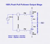
Here is an idea to accomplish arbitrary amounts of single-ended bias in the output stage. Shown is only 1/2 of a full balanced bridged output stage. The three images shown from left to right are three different configurations, whose only difference is the manner in which the NMOS and PMOS gates are driven.
Left: 100% Push Pull ala BA #2
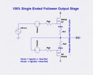
Middle: 100% Single Ended using complementary output devices
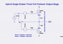
Right: Hybrid of Push Push and Single Ended
I have not run any simulations of the hybrid, but I think it would work.
Left: 100% Push Pull ala BA #2
Middle: 100% Single Ended using complementary output devices
Right: Hybrid of Push Push and Single Ended
I have not run any simulations of the hybrid, but I think it would work.
Attachments
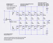
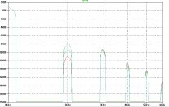
Here is an LTSpice simulation of the Hybrid PP/SE output stage. The parameter Alpha controls the potentiometer mixing between PP and SE. Alpha=0 is total push-pull. Alpha=1 is total single-ended.
The plot shows the harmonics for 3 values of Alpha:
The plot shows the harmonics for 3 values of Alpha:
- Color Alpha THD %
- Green 0.0 0.0043
- Red 0.3 < 0.001
- Blue 0.35 0.0014
Attachments
Here is an LTSpice simulation of the Hybrid PP/SE output stage. The parameter Alpha controls the potentiometer mixing between PP and SE. Alpha=0 is total push-pull. Alpha=1 is total single-ended.
The plot shows the harmonics for 3 values of Alpha:
- Color Alpha THD %
- Green 0.0 0.0043
- Red 0.3 < 0.001
- Blue 0.35 0.0014
Green has a higher THD BUT look at the harmonic spectra structure...
Of course this is preceded by the 1992 Aleph 0. Later the early version of
the Aleph 1 used a little different technique for modulating the current source,
but I abandoned it for the 2 stage circuit of the later Alephs.
- Status
- This old topic is closed. If you want to reopen this topic, contact a moderator using the "Report Post" button.
- Home
- Amplifiers
- Pass Labs
- XA.8 single-ended current sources