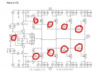
I hope those PS caps will find a better way of connecting those wires.
Or maybe you were just in a hurry to get it up and going?
Regards
David
Are you refering to the pics shown?
Not sure what you mean?
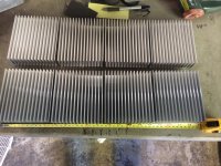
Heat sinks arrived.
Larger and more weight than I had actually anticipated

I will have an inch gap between the upper and lower row of sinks. This is part design and part to help inject fresh air into the second row of sinks. I have read that as the height of the sink increases the efficiency decreases, so hoping this helps a little. Rough layout of what would be each side of each monoblock.
I will cut off a little of each side of each sink to keep consistent look and will use half of another heatsink on each row to get 19" of consistent length, that's why I ordered 38 pieces.
Now on to cutting the tops, bottoms, fronts and backs out of 1/8" aluminum plate.
Larger and more weight than I had actually anticipated

I will have an inch gap between the upper and lower row of sinks. This is part design and part to help inject fresh air into the second row of sinks. I have read that as the height of the sink increases the efficiency decreases, so hoping this helps a little. Rough layout of what would be each side of each monoblock.
I will cut off a little of each side of each sink to keep consistent look and will use half of another heatsink on each row to get 19" of consistent length, that's why I ordered 38 pieces.
Now on to cutting the tops, bottoms, fronts and backs out of 1/8" aluminum plate.
I see you and BigE are both in the same city, a shoutout is possible!
Oh, I am sure it will happen. However, our amps will be somewhat different, mine being a lower powered stereo version.
The heatsinks I purchased have smooth outside side fins and the internal fins are serrated. So at each splice I cut the smooth sided fins off, and in the correct location to maintain even fin spacing for the entire length of each section of heat sink.
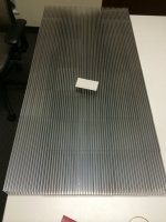
Here is all the heatsink laid out (business card for reference). Pretty massive and to think this is all going to be so hot you can only touch for a few seconds? Almost makes you want to rethink this!
Based on the heatsink used in each DIY 5U chassis I have about 50% more square inches. Should be good to run up close to 150 watts?

Looking at your design, and the transformer you are planning to use. You will start to understand why I decided to split the monoblock into 2 chassis.
What you have drawn there with the trafo and all those heatsinks per monoblock, you will need a forklift to move that amp.
Also, since you want to try and bias that amp to 150W, you need a lot of air circulation not only on the outside, but also the inside as well. Note that the trafo will generate heat on its own too. Be careful with internal temperature. With that layout, I doubt you will hit 150W without the sinks surpassing 55 - 60C or above 25-30C above ambient, unless you want to store your amps outside in the winter
Since you decided to up the caps to 448kuF per, you are definitely going to need a slow charge circuit on top of the soft start. If you don't, your turn on spike will be in excess of 60A, and it won't lower to under 10A for quite a number of cycles. This will blow your house fuse and other components in the amp. The Soft start will NOT be enough. You may want to follow a few of the threads on the power supply section. There are a number of designs that would work for you. I used a very simple RC constant timer , but BigE and a number of others are discussing the use of a 555 timer which although more complicated, perhaps more suited.
Last edited:
Andrew, thanks for commenting on my plans so far. I hope you don't mind if I pick your brain from time to time? What you have done is the closest build to what I had in mind. My exterior design might hold me back from getting to a full 150w. I do have two 13" subs with 500w each internal amps, so I already have some punch available. But if your going to build something it doesn't take that much extra to have extra, right?Looking at your design, and the transformer you are planning to use. You will start to understand why I decided to split the monoblock into 2 chassis.
What you have drawn there with the trafo and all those heatsinks per monoblock, you will need a forklift to move that amp.
Also, since you want to try and bias that amp to 150W, you need a lot of air circulation not only on the outside, but also the inside as well. Note that the trafo will generate heat on its own too. Be careful with internal temperature. With that layout, I doubt you will hit 150W without the sinks surpassing 55 - 60C or above 25-30C above ambient, unless you want to store your amps outside in the winter
Since you decided to up the caps to 448kuF per, you are definitely going to need a slow charge circuit on top of the soft start. If you don't, your turn on spike will be in excess of 60A, and it won't lower to under 10A for quite a number of cycles. This will blow your house fuse and other components in the amp. The Soft start will NOT be enough. You may want to follow a few of the threads on the power supply section. There are a number of designs that would work for you. I used a very simple RC constant timer , but BigE and a number of others are discussing the use of a 555 timer which although more complicated, perhaps more suited.
I understand that I'm going to have to add some additional complexity for slow and soft start systems.
Where/what did you get matched mosfets?
I read some of your posts on Canuck. What positions did you you use nudies? That's what I used in my preamp for all the resistors in the signal path. The plan calls for .5w and the nudies are rated at .4, any issues?
Depending on which mosfets, I got the FQA's from Buzzforb here on a GB.
If you want toshiba's then zhoufang, via his ebay account these days, if you can get a hold of him...
I used the TX2575's in R1 and R13 (and its corresponding mirrors)
Thanks for the quick reply.
You used the FQA's, any reason not the Toshiba's?
Have you started building the second pair? Any changes contemplated?
Since I'm a "DIY in training" can you confirm for me (and others who might know less than me) these locations for the nudes? I'm assuming you used 47r instead of the 47r5's? I have a pair of 1k2 nudes left from another project, do you think these will be ok in place of the 1k for position R1?

There is no reason not to use the toshibas. I just wanted to try the FQA's. The second one I'm building I'll be using the Toshiba's, then I'll get to race them 
I have enough to do swaps, depending on which one sounds better
Yes the locations you pointed out is where I decided to use the TX2575's.
I used 47r5 as per schematic.
I don't know enough about circuit design to say that a 1k2 would work just as well as the specified 1k. Perhaps someone else on the forum may be able to tell you what a higher resistance would do....
Note that there are a lot of combinations of resistor brands etc that you can use to customize the sound. Since some here may say that its bogus, I won't advocate to use certain brands over another... but in my experience with the F5, I hear differences. The nudes aren't the only resistors I changed from even the GB premium set.
Last edited:
There is no reason not to use the toshibas. I just wanted to try the FQA's. The second one I'm building I'll be using the Toshiba's, then I'll get to race them
I have enough to do swaps, depending on which one sounds better
Yes the locations you pointed out is where I decided to use the TX2575's.
I used 47r5 as per schematic.
I don't know enough about circuit design to say that a 1k2 would work just as well as the specified 1k. Perhaps someone else on the forum may be able to tell you what a higher resistance would do....
Note that there are a lot of combinations of resistor brands etc that you can use to customize the sound. Since some here may say that its bogus, I won't advocate to use certain brands over another... but in my experience with the F5, I hear differences. The nudes aren't the only resistors I changed from even the GB premium set.
I don't see 47r5 nudes listed as for sale. Did you custom order?
Every part can make large or small differences. Sometimes more expense parts do no not sound (subjective) as well as some less expensive ones. That's one of the problems with DIY, manufacturers have the ability to spend countless hours researching components to achieve a certain sound/price point, DIY'ers not so much. But at least DIY'ers can compare and exchange preferences to help some. The nudes are one of those parts that seem to review well.
Last edited:
Every part can make large or small differences.
True.
But no passive part makes a much difference as the proper adjustment of P3.
I don't see 47r5 nudes listed as for sale. Did you custom order?
.
Yes I ordered directly from Texas Components.
I also went all the way and got the metal foil trim pots as well instead of the bourns.
Thanks for commenting. I had to read up to see what "proper adjustment of P3" was. Still at the part buying, chassis building stage. You detail this step well in your tutorial, thanks.True.
But no passive part makes a much difference as the proper adjustment of P3.
I hope you will continue to comment as I move forward, I need all the help I can get.
Thanks for the reply. I thought I was loosing my shopping ability, I couldn't find those values anywhere. Then after I went directly to Texas Components site and saw they offer to custom make to your spec I thought that's what you must have done.Yes I ordered directly from Texas Components.
I also went all the way and got the metal foil trim pots as well instead of the bourns.
Thanks for the reply. Since I'm just at the chassis building and parts buying stage, I had to research what you meant by "P3".True.
But no passive part makes a much difference as the proper adjustment of P3.
Good to know! I hope you continue to advise when I get to that stage.
Thanks for the reply and reinforcing the DIY spirit of community!You bet! And feel free to contact me or ask the forum any questions you have during any stage.Remember, the only stupid question is the one you don't ask.
We all want you to have a successful build.


I could use some help in sourcing matched 2SK1530 & 2SJ201's. I have found a few sources for them, but not matched. I'm not sure if I'm up to trying myself. I found "Tech-DIY" that sells matched pairs. I have asked about matching process and a set of matched octet. Any experience with them? I have not received a reply yet.
Jack's a great guy to deal with. Tech-DIY is his hobby business, so sometimes response is slow-ish.
BTW, you don't need an octet per se, you need a quad each of K1530 and J201 per amp. There is little reason to do a strict N to P match.
Also, if those are unavailable, don't shy away from the IRF parts, that's what's used in most of the factory Pass amps...
BTW, you don't need an octet per se, you need a quad each of K1530 and J201 per amp. There is little reason to do a strict N to P match.
Also, if those are unavailable, don't shy away from the IRF parts, that's what's used in most of the factory Pass amps...
Thanks for the info on Tech-DIY, I just ordered two quartets of the 2SK1530 & 2SJ201's.Jack's a great guy to deal with. Tech-DIY is his hobby business, so sometimes response is slow-ish.
BTW, you don't need an octet per se, you need a quad each of K1530 and J201 per amp. There is little reason to do a strict N to P match.
Also, if those are unavailable, don't shy away from the IRF parts, that's what's used in most of the factory Pass amps...
My 8ea Evox Rifa 82,000uF caps shipped today.
- Status
- This old topic is closed. If you want to reopen this topic, contact a moderator using the "Report Post" button.
- Home
- Amplifiers
- Pass Labs
- Aloha F5 v3 Monoblock build