Looks fantastic, man! Good job!
Thanks! Finished up the rest of the amp boards over the weekend, now I'm fine tuning the layout in preparation to start wiring things up.

Hi guys, back and still in black. I’m still looking for some direction on my F5Tv2. Last night I started removing my boards from the F5T. I was going to start removing the resistors to be changed. Remember I was saying how I couldn’t explain how a 120 ohm resistor was slotted at positions R-25 & R-26? Well when I got the boards out and those resistors removed, the color coding is horrible. My wife actually confirmed the colors which would’ve given me 120 ohm resisters but when I checked them, they are actually 10k which is what the schematic shows. So the question is, what else can make those MOSFET’s get that hot? I did take some voltage readings but I’m not sure if I should be taking across the resistor or reading from the resistor to ground which is what I did.
You measure across the resistor with amp turned off.
Not sure how to help you along, I would take advice from someone really knowing this circuit. I only know it from manual and scouring the forum.
I think I would start with measuring all the resistors on the front end boards this way. Also, I would double check that all transistors are mounted the correct way.
Sorry, man.
Last edited:
Andynor, thank you anyway. I should’ve been more clear, I was talking about measuring a voltage that would be hitting the Q7 & Q8 transistors.
Either your cascodes are:
1: The wrong parts and / or you have switched N for P channel cascode fets.
2: You are getting double voltage due to faulty wiring (unlikely since nothing has exploded)
3: More likely, your cascodes have too much bias.
So do the following:
1: Confirm values of R25, R27 and R29, and R26, R28 and R30, for both front end boards. Post here.
2: Confirm the correct cascode transistors are in the correct place, with correct orientation
3: Confirm correct rail voltages into the front end (v+ to gn, v- to gnd).
Hopefully this will provide an explanation for your issue and hence the solution.
Cheers,
Andy
to luvrockin #745
Hello luvrockin,
I always measure my resistors with the DMM before they go into the pcb.
Because of matching from one channel to the other and because of easily
doing a mistake with the colourcode/ bands on the resistors.
It is easier with the DALEs but you can also make mistakes with their codes/
digits how many zeros....
I also made such mistakes... oh yea, I did!
Greets
Dirk
Hello luvrockin,
I always measure my resistors with the DMM before they go into the pcb.
Because of matching from one channel to the other and because of easily
doing a mistake with the colourcode/ bands on the resistors.
It is easier with the DALEs but you can also make mistakes with their codes/
digits how many zeros....
I also made such mistakes...
oh yea, I did!Greets
Dirk
Thanks guys! Andynor, good catch it totally makes sense with the coding but they are ridiculously hard to decipher the colors, even when out in there open. As far as the resistor values here goes,
R30=475 R26=10k R6=1k R28=4.75K R5=1k R27=4.75k R25=10k R29=475 ohms for the right channel and left. As for Q7 & Q8, I have a TIP31AG transistor on the V+ channel and the TIP32AG on the V- side and I confirmed this on both boards. The transistors are installed with the back of the transistors to the outside of the board, numbers on the MOSFET towards the inside of the boards. My rail voltage is +34.6 & -34.7vdc pretty much for both channels. Triple checked wiring and am not seeing anything with that to this point. You mentioned too much bias? I was turned on to a resistor tester by 6l6 earlier and I purchased it. I should have it Thursday. What I don’t know is how to check one of these circuits to find out how much voltage I have at a component, in this case Q7 & Q8, and how do I know how many volts should I have. Would that be done using ohms law?
@cubicincher, actual I did measure every resistor and picked values closest to those listed trying to keep values tight. That’s why this whole with the 120 ohms I was seeing wasn’t making sense because I didn’t remember that value when stuffing the boards, it’s not on the schematics, and that value wasn’t on any of my Mouser bills. I just figured I was losing it lol! I think Andynor nailed it and it never clicked until he posted above.
Hello luvrockin,
I always measure my resistors with the DMM before they go into the pcb.
Because of matching from one channel to the other and because of easily
doing a mistake with the colourcode/ bands on the resistors.
It is easier with the DALEs but you can also make mistakes with their codes/
digits how many zeros....
I also made such mistakes...
Greets
Dirk
Hi, Dirk! Do you see anything wrong with Luvrockins circuit in pics, and in those resistor values he posted?
Cheers,
Andy
Thanks guys! Andynor, good catch it totally makes sense with the coding but they are ridiculously hard to decipher the colors, even when out in there open. As far as the resistor values here goes,
R30=475 R26=10k R6=1k R28=4.75K R5=1k R27=4.75k R25=10k R29=475 ohms for the right channel and left. As for Q7 & Q8, I have a TIP31AG transistor on the V+ channel and the TIP32AG on the V- side and I confirmed this on both boards. The transistors are installed with the back of the transistors to the outside of the board, numbers on the MOSFET towards the inside of the boards. My rail voltage is +34.6 & -34.7vdc pretty much for both channels. Triple checked wiring and am not seeing anything with that to this point. You mentioned too much bias? I was turned on to a resistor tester by 6l6 earlier and I purchased it. I should have it Thursday. What I don’t know is how to check one of these circuits to find out how much voltage I have at a component, in this case Q7 & Q8, and how do I know how many volts should I have. Would that be done using ohms law?
@cubicincher, actual I did measure every resistor and picked values closest to those listed trying to keep values tight. That’s why this whole with the 120 ohms I was seeing wasn’t making sense because I didn’t remember that value when stuffing the boards, it’s not on the schematics, and that value wasn’t on any of my Mouser bills. I just figured I was losing it lol! I think Andynor nailed it and it never clicked until he posted above.
Hi, rockin!
Don’t give me credit I don’t deserve. It was he eminent and esteemed Mr. Hui that caught the color coding!
But what does Mr. Hui and 6L6 think of rockins problem? Does those resistor values provide any more insight?
I can not find a mistake in your cascode network resistors. It all looks fine to me.
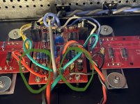
But taking a look at your front end capacitors, I stumbled upon a possible problem. Not sure if it is relevant for the cascode fet temp issue. But you should double check that all capacitors have the correct orientation
On the picture attached here, it looks to me like the following caps MIGHT be oriented the wrong way (plus to minus and vice versa):
C5
Possibly C6 (difficult to see)
Attachments
Last edited:
- Home
- Amplifiers
- Pass Labs
- F5Turbo Illustrated Build Guide