Pass DIY Addict
Joined 2000
Paid Member
Thermal grease is also required for the Aavid 4180G ceramic insulators. These have better thermal conductivity than mica or even (ungreased) Keratherm.
I couldn't agree more! Ceramic + grease is WAAAAY cheaper than Keratherm as well. Ceramic also resists those pesky little slivers of aluminum that can easily pierce Kerathem and ground your output mosfets.

Hi all, I have a quick question regarding grounding of the XLR inputs on Aleph J. I have two Alephs with balanced inputs only (no rca's) and have simply connected Pin1:Gnd Pin2:+in and Pin3:-in which seems to work just fine (only a slight hum if I stick my head in the speaker!) however I found a post on page 88 of this thread whilst browsing as a refresher (I'm about to build a 3rd Aleph J ") ) which seems to indicate that I should have my Gnd connected to the chassis and not to the board?
) which seems to indicate that I should have my Gnd connected to the chassis and not to the board?
) which seems to indicate that I should have my Gnd connected to the chassis and not to the board? Hi krath, the pin 1 is the shield of the XLR connector, must be connected to the chassis and not to the circuit ground. See: 3-1 Balanced Interconnections: Grounding ( Audio Component Grounding and Interconnection )
Why any manufacturer does anything does not help a DIYer understand or anyone learn.
Isn't thermal conductivity added like parallel resistors? From the manufacturers datasheets, a Kerathem pad it has a thermal conductivity of 6.5 W/mK. The Avvid 4180g has a thermal conductivity of 15 W/mK. High performance grease is about 2 W/mK. Assuming one layer of grease (correctly applied) and one 4180g together is equal to one Keratherm, the Keratherm is a better thermal conductor by 4.7 W/mK. The grease is the limiting factor.
Regardless, if a solution works for you, it works.
Isn't thermal conductivity added like parallel resistors?
You don't add thermal conductivity directly - it's just a material property - but thermal resistances are added like series resistors.
Here's a helpful explanation: 16.4 Thermal Resistance Circuits
Today, I took the opportunity of the containment to open my AlephJ to clean the dust inside (after five years of service, there was some).
I noticed that the sticker on the Toroïdy transformer slipped because it seemed that the glue melted. So, after checking bias and offset settings (both were still OK, no drifting after 5 years), I decided to checked the temperatures in my amplifier.
After 1 one hour (the time to check the settings), the transformer suface temperature was 50°C and inside air temperature was 39°C (measured with a cooking thermometer).
After 7 hours, I measured 66°C on the transformer and 43°C inside the amplifier.
My amp is a "classic" DIY AlephJ, nothing fancy, I just followed the BoM given in the first message of this thread. Same with the PSU:
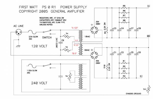
The transformer is a 300VA Toroïdy Supreme Grade (so it's encapsulated in epoxy and have a metal case).
Diode bridges are 35A Vishay (GBPC3502-E4/51 Vishay Semiconductors | Mouser France)
Here's a picture of the inside:

Do you think I have to worry about the transformer's temperature?
).I noticed that the sticker on the Toroïdy transformer slipped because it seemed that the glue melted. So, after checking bias and offset settings (both were still OK, no drifting after 5 years), I decided to checked the temperatures in my amplifier.
After 1 one hour (the time to check the settings), the transformer suface temperature was 50°C and inside air temperature was 39°C (measured with a cooking thermometer).
After 7 hours, I measured 66°C on the transformer and 43°C inside the amplifier.
My amp is a "classic" DIY AlephJ, nothing fancy, I just followed the BoM given in the first message of this thread. Same with the PSU:
The transformer is a 300VA Toroïdy Supreme Grade (so it's encapsulated in epoxy and have a metal case).
Diode bridges are 35A Vishay (GBPC3502-E4/51 Vishay Semiconductors | Mouser France)
Here's a picture of the inside:
Do you think I have to worry about the transformer's temperature?
Hi all, I have a quick question regarding grounding of the XLR inputs on Aleph J. I have two Alephs with balanced inputs only (no rca's) and have simply connected Pin1:Gnd Pin2:+in and Pin3:-in which seems to work just fine (only a slight hum if I stick my head in the speaker!) however I found a post on page 88 of this thread whilst browsing as a refresher (I'm about to build a 3rd Aleph J
Short answer: Pin 1 should go to the chassis. Not to audio GND.
Long answer: RANE Commercial - Knowledge Base
Short answer: Pin 1 should go to the chassis. Not to audio GND.
Long answer: RANE Commercial - Knowledge Base
Thanks mbrennwa, some good reading there!
Sorry that you're having some issues. Best advice at the moment may be to step away from it for a bit. A wise ZM once told me to take a tea break and come back with fresh eyes and calm heart. I have done similar things, and am a bit of a noob - so if below is too simple, my apologies. I never want to assume someone's skill level. Just trying to help.
After you come back from your break - and assuming you removed both amp boards from the heatsinks to make your changes...
1) Ensure that your amp boards have EITHER
the 1k resistor and the jumper at R6 OR
the pot you installed and the 562R at R6
I recommend the 1k and jumper, but that's me.
2) Blowing some fuses is a good thing vs. magic smoke. It is likely not a huge deal. So, deep breath. Check your fuses. Replace if necessary. Then, without the amp boards attached, do your dim bulb check again. If it doesn't pass the dim bulb - that's odd... but report back. I always do a dim bulb check if I take the boards off the heatsinks or disconnect boards from the PSU for any reason. I also check for shorts - see step 4.
If the PSU passes -
3) Check your unloaded voltages at v+ and v-. Pause here if they're not good and come back to the forum. If they're good move on.
4) Reset your pots on your amp boards. Install each board, but don't wire it yet. Check for shorts to the heatsink on all pins of the FETs. If there are any shorts - change your Keratherm or whatever you're using. Once there are no shorts... move on.
Wire one board and do a dim buib check. Disconnect that board and do a dim bulb check with the other board. If they're both good - wire both boards and do your final dim bulb check. If it passes ... move on.
5) Remove dim buib - deep breath - power up - Set bias and offset. Report results. Hopefully with a big smile.
ItsAllInMyHead,
Thanks for the suggestions. I'm still having the same problem. I've made some notes based on your comments, below,
1. I've installed the 1k resistors.
2. Passed the dim bulb check unloaded.
3. The unloaded voltages were all the same 25.6v and look very good.
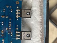
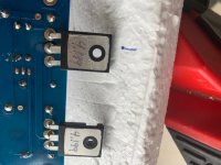
4. I didn't see any shorts. kilohertz comments noted I should trim the leads, so I did that where potentially appropriate, too. I checked the keratherm and there were some scratches/tears in two of the pads so I replaced them. If you see the attached photos there is some bubbling on the underside of the transistors where the keratherm was bad. Does this mean these two transistors were fried? I had originally purchased these from the DIYAudio store in Aleph J kit, matched.
I powered up the amp with one board attached at a time. The good board is still good and passes the bulb test. The bad board is still bad and the bulb stays lit.
Next steps?
Thanks
/d
Attachments
ItsAllInMyHead,
4. I didn't see any shorts. kilohertz comments noted I should trim the leads, so I did that where potentially appropriate, too. I checked the keratherm and there were some scratches/tears in two of the pads so I replaced them. If you see the attached photos there is some bubbling on the underside of the transistors where the keratherm was bad. Does this mean these two transistors were fried? I had originally purchased these from the DIYAudio store in Aleph J kit, matched.
I powered up the amp with one board attached at a time. The good board is still good and passes the bulb test. The bad board is still bad and the bulb stays lit.
Next steps?
Thanks
/d
1-3: Great news.
4: Rats. Yep, you most likely have at least one blown output device due to (maybe) the MOSFETs shorting to the heatsinks. It's odd that you didn't see a short in your testing prior to running the dim bulb check on the "bad" board. Did you check it before or after re-mounting with the new Keratherm? If there was no short to the chassis from (likely the drain / pin 2) - then that points to a different root cause somewhere else possibly. The heat from the MOSFETs going up could have caused the holes or the holes could have contributed to the MOSFETs going up.
Out of an abundance of caution, I should let someone else recommend next steps. I am unsure how (or if) the MOSFETs can be tested in situ. Before advising to replace them due to simply looking at them... someone may have a suggestion for checking them while in place or even after removing them to see if you need new parts.
If it comes to replacing them - I'm also not exactly sure how tightly they should be matched. That writing looks familiar, so I'm guessing you got a kit from the store and don't have spares? Either way, you'll get it sorted soon. Someone will chime in soon with suggestions, I'm sure.
Best of luck on getting it fixed! It's truly a wonderful amp, IMO.
By shorts I assume you mean the the leads were touching the heatsink. No, there weren't any I saw. But then again, I can't see through the MOSFETS to the keratherm where damage may have occurred because of tears/holes in the material.
I don't know how to test the MOSFETS. Is there something in one of the boards how to do this? I couldn't find anything because "test MOSFETS" gives way too many results. Jim had something one for testing other kinds of transistors with a 9v battery and a volt meter, but i don't know if it would work here.
Frankly, this is really frustrating. My M2x (and every other Pass project I've completed) is running without any problems whatsoever, and I can't get this channel working no matter what I do.
Thanks,
/d
This morning, while reading the BA-3 build guide, I found something interresting concerning my transformer's temperature:
(0.4/0.47)*24*8=163W. So the transformer should be 330VA minimum, if I understand correctly.
Mine is a 300VA, so a little bit under the minimum recommended VA. Do you think it could be the explanation of the fairly high temperature I measured?
By the way, I think it could be useful to put the above explanation about tranformer's VA choice in the first message of the AlephJ mounting guide. It will help beginner, I think (if I had read this when I began my build, I would have bought a 400VA transformer).
For the AlephJ, the calculation is:TRANSFORMER = The amplifier’s total bias (in Watts) should be no more than 1/2 the VA of your transformer.
How do you determine watts? Simple - measure your bias current, the voltage drop across the 3W source resistors. Let’s say you measure .3V . Divide that by the value of the source resistor. If using 1.0 ohm, your answer is then .3A (.3 / 1 = .3) — but if using 0.47ohm resistors, a voltage drop of .3 is now .64A (.3 / .47 = .637) Back to the example using the 1.0 ohm resistors, multiply by your rail voltage, 32V, so each device will have a bias of 9.6W (.3 * 32 = 9.6) then multiply by the number of devices - 12 in this amp, (12 * 9.6 = 115W)
(0.4/0.47)*24*8=163W. So the transformer should be 330VA minimum, if I understand correctly.
Mine is a 300VA, so a little bit under the minimum recommended VA. Do you think it could be the explanation of the fairly high temperature I measured?
By the way, I think it could be useful to put the above explanation about tranformer's VA choice in the first message of the AlephJ mounting guide. It will help beginner, I think (if I had read this when I began my build, I would have bought a 400VA transformer).
By shorts I assume you mean the the leads were touching the heatsink. No, there weren't any I saw. But then again, I can't see through the MOSFETS to the keratherm where damage may have occurred because of tears/holes in the material.
I don't know how to test the MOSFETS. Is there something in one of the boards how to do this? I couldn't find anything because "test MOSFETS" gives way too many results. Jim had something one for testing other kinds of transistors with a 9v battery and a volt meter, but i don't know if it would work here.
Frankly, this is really frustrating. My M2x (and every other Pass project I've completed) is running without any problems whatsoever, and I can't get this channel working no matter what I do.
Thanks,
/d
Nope - I meant - Taking a DMM set to continuity (or similar) and with one probe on the heatsink or touching one of the mounting bolts for your MOSFETs or anything running to the heatsink and moving the other probe between all 3 legs of the MOSFET. It should show "Over Limit" and/or Not Beep. It's not a visual check.
You'll need to wait for someone with a bit more brains than me to help you sort how to test the MOSFETs themselves. If it were me... I'd yank them and test them. There a a few methods I've read, but even I would "phone a friend" and wait for an answer from someone here that can definitively provide a solid approach. In the interim - Papa has a ton of great articles on the First Watt site. I have been slowly moving my way through them. Some are still over my head, but I learn a bit each time. This one may be a good one to get you going if you haven't read them yet.
http://www.firstwatt.com/pdf/art_mos_test.pdf
The only two methods I know are the "DMM set to diode" test for a super quick "is it totally toast" and running each of them through a check for Vgs described in the article above. It's also how I learned to match MOSFETs for Vgs (but I still am learning more and more characteristics). I'm confident there are better ways for you to check. Someone may even have a suggestion for how to check them w/o removing them. My guess though is that sadly, they're probably toast.
Yep, it's frustrating. My first few builds went well, until one didn't.
I was told releasing the magic smoke is a right of passage. It still sucks every time I do it. However, every time I do it, I learn a bit more about how the circuit works, I'm a bit more careful in understanding the schematics and asking questions on my next build, and I get a bit more knowledge re: troubleshooting. So, there is an up side. If I spot anything from a reliable source re: testing for this specific situation, I'll post. Did you read back in the thread? I can't believe you're the first to smoke a set and post about it.
One thing to consider is that one of each pair has shown bubbling on the
back. So even if that mosfet is not toast, you will have difficulty getting full contact
with the heat sink, and it will likely eventually fail.
I think it's likely will you need two new pairs of mosfets.
Fortunately IRFP240 is a common part so it should be easy getting
new pairs. Alternatively you may take this as an opportunity to
learn to measure and match mosfets. Make lemonade out of lemons.
I know it's frustrating, but you will get this working eventually.
Today, I took the opportunity of the containment to open my AlephJ to clean the dust inside (after five years of service, there was some
I noticed that the sticker on the Toroïdy transformer slipped because it seemed that the glue melted. So, after checking bias and offset settings (both were still OK, no drifting after 5 years), I decided to checked the temperatures in my amplifier.
After 1 one hour (the time to check the settings), the transformer suface temperature was 50°C and inside air temperature was 39°C (measured with a cooking thermometer).
After 7 hours, I measured 66°C on the transformer and 43°C inside the amplifier.
My amp is a "classic" DIY AlephJ, nothing fancy, I just followed the BoM given in the first message of this thread. Same with the PSU:
The transformer is a 300VA Toroïdy Supreme Grade (so it's encapsulated in epoxy and have a metal case).
Diode bridges are 35A Vishay (GBPC3502-E4/51 Vishay Semiconductors | Mouser France)
Here's a picture of the inside:
View attachment 833243
Do you think I have to worry about the transformer's temperature?
Your transformer may be running a little hot. I have the same transformer in my Aleph though I’m running mine at slightly higher rail voltages then most. I’ll swap amps out this weekend measure the temps on mine and report back
After I posted my last comment I figured I’m working from home so why not just plug the amp in and let it bake. I had it one for a little over 6hrs. I have my bias at .420 and run mine hot to the point my sinks fluctuate between 55-57 degrees Celsius. My unloaded rails are a little over 29 volts and after measuring the temp on my transformer, it got no hotter than 50 degrees Celsius
- Home
- Amplifiers
- Pass Labs
- Aleph J illustrated build guide