Hi everyone!
It took a while, but now I'm back 🙂
I bought a test instrument Atlas DCA55, (really nice actully!, I recommend you to buy one by yourself), and meassured all the ZTX450, 550, but them seem's ok to me. I tested IRF9610 and 610 as well. (also rechecked orientation of all transistors, all resistor was placed correctly).
After that, i really think the preamp board are ok after all!
I have reversed cables and reconnected the volume/inlet control boards and get the volume up a bit, so my focus are right now on the grounding of all signal connecting.
If anyone has an idea, you are welcome to share your experiense please!
I put 680ohm resistor where the 2K pot. are intended to be, (as instruction says), and I will test a 2K pot. too, to set up gain level.
I didnt have much time a week for this, but I will try to keep up so this will be solved.
Thank you all for trying helping me!
Best regards, Mikael
No special meter is needed to test which lead is which on bi-polars. It can be done with a simple VOM in the X100 mode.
Hi all.
New to this section of the forum.
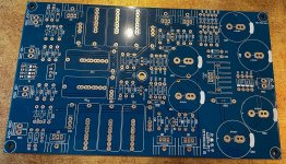
I`m building one of these based on attached pcb. I have two, one`s now assembled but I have no output. I`m aware they are clones of the design, but simply didn`t knew when I bought them. Quality seems okay, I have traced all connections on the board and they should be fine.
All parts double checked for correct value, position and orientation in the position.
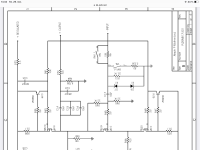
Situation: No output despite following the reference to the original Pass schematics:
Input: 0,9 volt 500 Hz from 600 ohm signal generator.
Stable 60 vdc after the 3,3 ohm resistor
All switches in open position
Q 19: Drain (D) 35 vdc, Grid (G) 0,6 vac, Source (S) 15 vdc
Q 20: D 13,5 vdc, G 4,5 vdc, S 1,5 vdc
Q 14: C 4,5 vdc, B 0,6 vac, E 0 (connected to ground so that should be correct off course)
Q 13: E 60 vdc, B 60 vdc, C 56 vdc
Q 18: 60 vdc, G 56 vdc D 34 vdc.
Trim pot adjusted to equal avalues within 10 ohm
Values are identical for both channels.
I do have a sinus shaped 5 mv ac detectable at the output, but that`s all.
My focus has been around Q 14 450 npn but I simply can`t crack the reason.
Your help and assistance will be highly appeciated.
Kind Regards
Thomas
New to this section of the forum.
I`m building one of these based on attached pcb. I have two, one`s now assembled but I have no output. I`m aware they are clones of the design, but simply didn`t knew when I bought them. Quality seems okay, I have traced all connections on the board and they should be fine.
All parts double checked for correct value, position and orientation in the position.
Situation: No output despite following the reference to the original Pass schematics:
Input: 0,9 volt 500 Hz from 600 ohm signal generator.
Stable 60 vdc after the 3,3 ohm resistor
All switches in open position
Q 19: Drain (D) 35 vdc, Grid (G) 0,6 vac, Source (S) 15 vdc
Q 20: D 13,5 vdc, G 4,5 vdc, S 1,5 vdc
Q 14: C 4,5 vdc, B 0,6 vac, E 0 (connected to ground so that should be correct off course)
Q 13: E 60 vdc, B 60 vdc, C 56 vdc
Q 18: 60 vdc, G 56 vdc D 34 vdc.
Trim pot adjusted to equal avalues within 10 ohm
Values are identical for both channels.
I do have a sinus shaped 5 mv ac detectable at the output, but that`s all.
My focus has been around Q 14 450 npn but I simply can`t crack the reason.
Your help and assistance will be highly appeciated.
Kind Regards
Thomas
Attachments
@ttp I have those boards as well and I think I got audio from them (it's been a while and they are packed away now so I can't check). Can't really find your parts references on the board though - where are you measuring? Also, which parts did you use for the small-signal devices and where did you get them?

Hi again.
A bit of news but unfortunately same situation.
I decided to scrap the initial pcb, remove the caps for use again, procure a new batch of transistors
and some nice 1% Vishay/Dale reistors and build the second pcb. Resistors came in two physical sizes
despite ordered with the same power rating.
Cross checked all values, of components build the pcb and checked for the usual faults such as short circuits and incorrect
location of components.
Still no output!
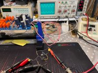
I can trace the 1vac input to the Source side of the first mosfet (IRF610) and have symetrical dc voltages across the rest of the transistors at both channels but that`s about it.
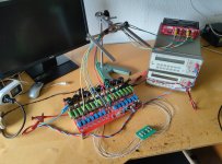
I actually build a little test set-up and checked one of the mosfets (610) from the first pcb, and as you can see it works as it should.
Hope someone can assist where to look for the fault as I am at the end of my capabilities.
A bit of news but unfortunately same situation.
I decided to scrap the initial pcb, remove the caps for use again, procure a new batch of transistors
and some nice 1% Vishay/Dale reistors and build the second pcb. Resistors came in two physical sizes
despite ordered with the same power rating.
Cross checked all values, of components build the pcb and checked for the usual faults such as short circuits and incorrect
location of components.
Still no output!
I can trace the 1vac input to the Source side of the first mosfet (IRF610) and have symetrical dc voltages across the rest of the transistors at both channels but that`s about it.
I actually build a little test set-up and checked one of the mosfets (610) from the first pcb, and as you can see it works as it should.
Hope someone can assist where to look for the fault as I am at the end of my capabilities.
Attachments
Trying to calibrate the aleph p1.7.. it is not as easy as it sounds when everything is a compromise, we all want low dc offset low thd , correct gain and equal.. luckily i got this qa403, now i can monitor thd levels real time while adjusting bias levels and gain...
Where. Is the magic sweetspot?.. what current should i be seeing across 3r3? How about the offset? All interacts in aleph
Where. Is the magic sweetspot?.. what current should i be seeing across 3r3? How about the offset? All interacts in aleph
Attachments
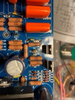
I noticed some DC offset in the current mirrors of my Aleph P1.7 preamp: about 60 mV in the left channel and as much as 300 mV in the right after 30 minutes of warm-up. I suspect the 2SA970 and 2SC2240 transistors I used, as I didn’t match them at all – I just soldered them in because the silkscreen said so.
Today, I decided to take a more systematic approach. I carefully matched new sets of BC549C (NPN) and BC559C (PNP) transistors to replace the originals. V<sub>CE</sub> during testing was close to their maximum, but I’ll give them a try. I’ve picked out 4 of each that are extremely close in hFE – probably as good as I’ll get without expensive dual monolithic pairs!
I also found the 200 Ω gain trimmer a bit too limited, so I’ll solder in a 500 Ω trimmer today. This will give me much finer control to set the gain precisely where I want it.
My plan is to set the preamp’s gain with a 4 V RMS balanced input, aiming for 8–10 dB gain. This matches what most balanced DACs put out and should give the best compromise between noise floor and output headroom. Once the gain is dialed in, I’ll take detailed FFT plots to see how the 2nd and 3rd harmonics distribute – and check exactly what DC offset remains.
This will give me a clean baseline, so I can hear and measure exactly what the new matched pairs – and maybe even some thermal tweaks – bring to the table. Let’s see how far I can take this!
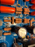
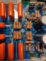
I’ve installed carefully matched BC549C (NPN) and BC559C (PNP) transistors in the right channel of my Aleph P1.7 preamp. I also replaced the 200 Ω gain trimmer with a 1 kΩ unit for finer adjustment control. The left channel remains untouched, still using the original 2SA970/2SC2240 transistors and a 200 Ω gain trimmer.
Before making the swap, I measured the Vce across the original transistors to ensure the BC pairs (which only tolerate 30 V) would be safe in this circuit. Vce was consistent across all relevant positions at around 0.6 V – well within safe limits for the BC devices.
Previously, the right channel had a DC offset of around 300 mV (before the output coupling capacitor). After the update, here are the DC offset results:
Right channel (new BCs, 1 kΩ trimmer):
• Trimmer fully counter-clockwise: 25 mV
• Trimmer fully clockwise: 120 mV
Left channel (original 2SA970/2SC2240, 200 Ω trimmer):
• Trimmer fully counter-clockwise: 111 mV
• Trimmer fully clockwise: 200 mV
Note that the input was not fully shorted to ground during these measurements – only via the piano switch (3k32 to ground).
The right channel now shows a significantly lower and more stable DC offset, likely due to the matched pairs and improved trimmer range. Next, I’ll measure both channels with the QA403 audio analyzer for a thorough A-B comparison of distortion spectra (2nd/3rd harmonics), noise floor, and DC offset stability. I’ll also upload screenshots of these A-B measurements for those interested in the detailed data.
Hi Erland.. transistors are not fake.. they are mis matched, mismatched differential mirrors generate higher thd and more odd harmonics,, they function best balanced. Sure the blocking caps remove the dc, one could think everything is honkyddory, well it is until you test the circuit.
Photo is from right channel with matched transistors, it behaves nicely , gain is not set yet, was just playing.

Photo is from right channel with matched transistors, it behaves nicely , gain is not set yet, was just playing.
And since the aleph is single supply and not bipolar , theres no way of getting around coupling capacitors..
From the screenshot above you can see
Left channel with unmatched 2sa970 2sc2240 transistors shows THD+N around -48 dB (~0.4%), clearly reflecting the effects of transistor mismatch with higher noise and distortion.
Right channel, with matched BC549C/BC559C pairs, significantly improves performance, reaching THD+N around -77.5 dB (~0.013%).
All theese figures are not totally dependable yet as gains are not fully set, but the difference is not able its 2900 percent less noise in right versus left.. but as said numbers are not useful yet..
Here are a few measurements from today..
Looking at the numbers, i feel a bit meeh, but i have not actually listened to it yet, might sound great.
Thd is not totally alike, might play with current mirrors a bit more,
1vrms in 9db gain .. something like 2.8vrms out
Cross talk touches minus 80db..still good,
Frequency response pretty linear from 20 to 3khz. Down a few db around 10-20khz..
- Home
- Amplifiers
- Pass Labs
- Pass Aleph P 1.7 preamp builders thread