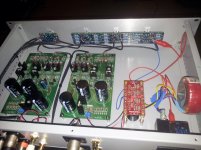
So I have one board heatsinked and its working good EXCEPT my regulator was only giving me 48 volts to the preamp circuit. My raw DC is just shy of 80 volts so that's not the issue. I added one more zenerto the string and that brought it to 58 volts which is very close to optimum. Actually, the IS now 60 volts on the regulator mosfet and accounting for a couple volt drop this is normal. Also, the less voltage the regulator has to drop the cooler it runs. My heatsink's get warm but not hot after a half hour.
Mark
Edit: Fixed regulator problem. One Zener was in reversed. Now I also have ~58 volts.
Mark, the boards look good. I was going to suggest one zener could be shorted or in backwards. I didn't see the edit on the original subscriber notice of your post. Just for a reference point for others trying to figure out heat sinks, how warm do the 4 FETs get with that heatsink?
I would prefer to have them warm rather than hot. I have a number of options, including heat sinks similar to what you used, but haven't decided what to use yet. I am currently working on an Aikido preamp and need to get that completed before moving on to something else.
I'm wondering what everybody will be using for gain and attenuation control and also for a chassis to put it in.
Brian: for attenuation you already know: I have dantimax relay attenuators.
for the chassis: I bought Galaxy388 from DIYaudio store. I am only thinking about swapping the bottom plate for a thicker one since I have an oversized Xformer.
fet temp: I did not measure but on touch the main heatsink was nicely warm. this was with 1kOhm load. the way you matched them (at only 30degC?) I 'd say I probably have the right heatsink for the job; in summer the temp may still go over though.
--------------
Mark Allen: looking good!! I am envious that your regulator fet can make it with that tiny heatsink? my oversized plitron Xformer (2x60V 120VA) is outputing over 90V (I have no idea how they size them), so my reg fet can only make it screwed to the bottom of the chassis.
for the chassis: I bought Galaxy388 from DIYaudio store. I am only thinking about swapping the bottom plate for a thicker one since I have an oversized Xformer.
fet temp: I did not measure but on touch the main heatsink was nicely warm. this was with 1kOhm load. the way you matched them (at only 30degC?) I 'd say I probably have the right heatsink for the job; in summer the temp may still go over though.
--------------
Mark Allen: looking good!! I am envious that your regulator fet can make it with that tiny heatsink? my oversized plitron Xformer (2x60V 120VA) is outputing over 90V
(I have no idea how they size them), so my reg fet can only make it screwed to the bottom of the chassis.
Last edited:
Koja,
The more voltage you drop across the mosfet the hotter it's going to run. My raw supply is almost exactly 80 volts with 120 volts mains. I have another 1.7 here that has same heat sink on the regulator and it does get hot to the touch but not extremely hot. The new board is about the same temperature. I am using Avel D4007 transformer on both. The original P factory version had a little larger heat sink mounted flat on the pcb.
Bfpca, They only get mildly warm. I wish I had an IR heat thermometer. Perhaps I will head to harbor freight and get one today. Since I have not installed the sinks on the second board I can measure the fet's with no heatsink and with the ones I have on now.
BTW: I am not using an attenuator on the output I am using an attenuator on the input side. My Dynaudio's are only 89db so I do not hear any noise on the output even with my ear at the tweeters. I am using the Glassware Balanced Attenuator as I dislike all the digital circuitry running inside the chassis with the analog stuff. It's pretty hard to beat the quality of the Glassware Attenuator and its under 40 USD. I also use a Glassware Select 2 as a balanced selector switch. It will work either balanced or unbalanced as the hot and grounds are separate. It all wires in very neatly and works and looks exactly like the original Pass P did where there is a main gain control and left & right trims. I suppose the Glassware Attenuator could be used on the output as well. They sell it without resistors if you want to calculate your own. Those of you with very efficient speakers better stick to the output side!
For chassis I use Par-Metal. I will post pictures in a while.
Mark
Last edited:
Here is a picture of my present Aleph P. These boards were built by Mike W. I put them in a chassis with the proper D-4007 power transformer and selector-attenuator. It's a very good sounding unit. I do not have vinyl playback right now. I just use a Denon DVD-2900 as a CD transport with my own fully balanced DAC via balanced input (1). And to play back SACD and DVD Audio via an unbalanced input (2). My External DAC is fully balanced and has no analog output stage. Only a pair of Lundahl line transformers. The DVD-2900 is an old unit but still very exceptional player in it's own right and built like a tank. It's also very easy to mod or add a tube output stage to and the scanning lasers are dirt cheap and easy to replace.
The present boards have Elna Simlac II caps bypassed underneath because thats all there was room for. I wanted the new boards for all the real estate they have to allow trying other kinds of capacitors because I much prefer good film caps. I am starting out using the original caps that were factory installed in the P. But for the inexpensive cost of the Elna's they are not all that bad. I am leaving this line stage as it is and going to build a second one exactly like it. Same attenuator, input select and so on so I can compare the two.
The Par Metal Chassis is less than $70.00. The front and rear are aluminum and the rest is steel, so machining is easy. I used a Power Dynamics Power Entry module that has built in on-off switch and fuse holder to make electrical hook up quick and easy. Just put insulated crimps on the power transformer leads and connect them! This eliminates having another switch on the front panel and AC running around inside the unit if you want a power switch. Balanced connectors are gold plated Neutrick. RCA jacks are some gold plated ones I got locally here in town.
http://www.powerdynamics.com/filters/specs/HGN-337.pdf
Par-Metal
Edit: If you use one of these chassis be sure to use star washers under each screw. These chassis are powder coated and this will ensure that everything you screw together is connected for grounding. You can see some under the standoff's supporting the PCB's
Mark
Attachments
Last edited:
Here's my take on device temperature after running the boards for an hour. One heatsinked as in my pictures and the other one with only a heatsink on the regulator.
Q-23: It must be heatsinked. How much you will need depends on your raw DC. If you use the Avel 4007 toroid or equivalent then all you should need is what I show in my pictures. I can keep my finger on this heatsink for a long time.
Q-15 & Q-18: The pair together generate just about as much heat as the regulator does on my boards. So the pair should really be attached to a single heat sink as shown in my pictures. Cut off one lower fin to clear the two vertical resistors.
Q-16 & Q-19: These are the next hottest running devices. But even without a heat sink they only get very warm to the touch. Heat sink would be optional here.
Q-17 & Q-20: Neither get very warm to the touch. No heat sink really needed.
I opted to heat sink the four devices on both boards all together in a quad anyway because the backs of the devices are so close together, and I had the stuff already handy to do this. I speculate this will aid in quicker thermal stabilization and the preamp may also warm up and sound better in less time. It is also structurally much more solid to heatsink the pairs together.
None of these need to be attached to the chassis in any way. The only exception may be those using a much higher voltage transformer than the original design as you will be dropping more DC across the regulator. This is going to generate more heat.
Mark
Last edited:
Here's my take on device temperature after running the boards for an hour. One heatsinked as in my pictures and the other one with only a heatsink on the regulator.
Q-23: It must be heatsinked. How much you will need depends on your raw DC. If you use the Avel 4007 toroid or equivalent then all you should need is what I show in my pictures. I can keep my finger on this heatsink for a long time.
Q-15 & Q-18: The pair together generate just about as much heat as the regulator does on my boards. So the pair should really be attached to a single heat sink as shown in my pictures. Cut off one lower fin to clear the two vertical resistors.
Q-16 & Q-19: These are the next hottest running devices. But even without a heat sink they only get very warm to the touch. Heat sink would be optional here.
Q-17 & Q-20: Neither get very warm to the touch. No heat sink really needed.
I opted to heat sink the four devices on both boards all together in a quad anyway because the backs of the devices are so close together, and I had the stuff already handy to do this. I speculate this will aid in quicker thermal stabilization and the preamp may also warm up and sound better in less time. It is also structurally much more solid to heatsink the pairs together.
None of these need to be attached to the chassis in any way. The only exception may be those using a much higher voltage transformer than the original design as you will be dropping more DC across the regulator. This is going to generate more heat.
Mark
For reference unheatsinked at 28°C ambient and running for 45 minutes:
Upper CCS (9610) : 80°C (could really do with a heat sink, but still well below max operating temp of 150°C)
Gain MOSFET: 60°C
Lower CCS: 51°C
Heat-sinked (small finned) PSU IRF610: 70°C
A post made by Klaus in 2004 re the P1.7 mosfets confirms Marks comments:
The upper CCS FET sees 62 – 27 = 35V at max. 30mA = 1.05W. Herefor I use a small heat sink, a stick o type for lowest thermal capacity = warm up time.
The middle signal FET lays between 27 and 9V at 20mA, so 0.36W – a cool number w/o any measure.
The lower CCS FET handles 9V to 0V at 20mA, so just forget it.
Is a seperate transformer for each channel way better then just one for the preamp?
Got some suitable transformers only they are 160VA. WAY OVERKILL i presume?
(also more chance of hum?)
Maybe use one and use the seperate windings? If it's way better to use two seperate transformers....i will have convince my wallet ;-) (or is it waf.....)
Got some suitable transformers only they are 160VA. WAY OVERKILL i presume?
(also more chance of hum?)
Maybe use one and use the seperate windings? If it's way better to use two seperate transformers....i will have convince my wallet ;-) (or is it waf.....)
Anyway, what would be a good voltage VAC transformer for this project???
Somewhere around 60volts AC. In my case I have the chassis and power transformer from a Philips CD960 cd player. The windings add up to just over 60volts and it's easily large enough to do the job. So that is my starting point.
Anything in the 20watt range or larger should do the job. The control circuitry will need it's own source of power.
- Home
- Amplifiers
- Pass Labs
- Pass Aleph P 1.7 preamp builders thread