I swapped the new boards for the old ones in my existing Aleph P. So they are working fine and they sound good. The only issue was the mounting holes are a tad bit too small for a 6/32 screw to pass through. So I had to enlarge them slightly. Perhaps they are for metric. I also wish there had been a spot to place a tiny LED on each pcb in the power supply. I am going to tack one in each board.
I have not fed 5 volts to the attenuators so I am at maximum attenuation at the moment. I'll do the 5 volt supply for the input attenuators tomorrow. I did not install the output relays on mine since my Aleph 2's are balanced.
Pictures tomorrow also...
Mark
I have not fed 5 volts to the attenuators so I am at maximum attenuation at the moment. I'll do the 5 volt supply for the input attenuators tomorrow. I did not install the output relays on mine since my Aleph 2's are balanced.
Pictures tomorrow also...
Mark
Yes, that's kind of what I figured... My preamp was already equipped with 6/32 and since the through plating doesn't connect to anything they are now 6/32 clearance holes. (#30 drill bit)
Mark
Mark
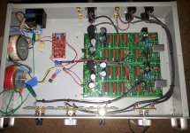
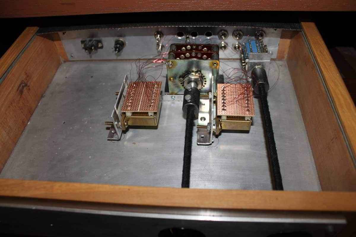
Ok, here it is at this point. These boards with these coupling caps sound great!
I am undecided on keeping the extra 5 volt supply in there. What I have now is temporary. I don't relay like the whole relay thing which adds unnecessary cost to the project and may just replace the input attenuator relay's with a small board with gold plated suitcase jumpers. Then I can dump the 5 volt supply. The relays are nice but they also complicate the whole thing, add about 50.00 to the cost and having to have a couple XLR jumpers to convert an input or output to unbalanced is irrelevant and uber easy. Gold plated suitcase jumpers will cost under a dollar! If this input attenuator were a practical front panel switch to add then perhaps... but once it is set I just don't need it.
If I decide to keep the 5 volt supply and the relays in this one I will make an extra circuit board that goes between the Transformers and the preamp boards for both the 5 volt supply, for junction of all AC and to route the 60 volts AC over to the two boards.
Mark
Attachments
Last edited:
That looks good Mark and I'm glad to hear that you are happy with the sound. There is a lot of room to customize the attenuation to whatever control scheme you choose. I am still undecided. I am thinking of using a double pole shorting type 12 position rotary switch to adjust the gain rather than a pair of pots. That way I won't need to worry about channel balance when adjusting 2 different controls. I still don't know what I'll do with the output attenuator.
I am only using attenuation on the input and it works great. This is a very quiet line stage! It's also pretty hard to beat the price of the Glassware Audio balanced Attenuator unless you get something from China. Thenkit is less than 40 USD. It could also be used on the output if one wanted to. It is completely customizable. Glassware has several options for different resistors or just buy the board and switches and use your own resistors.
You can save about $50.00 on the project by using suitcase headers on the input insead relays.
The more I listen to it the more I like it and the Panasonic capacitors are going to be hard for even the WIMA's to beat.
Mark
You can save about $50.00 on the project by using suitcase headers on the input insead relays.
The more I listen to it the more I like it and the Panasonic capacitors are going to be hard for even the WIMA's to beat.
Mark
I don't relay like the whole relay thing which adds unnecessary cost to the project and may just replace the input attenuator relay's with a small board with gold plated suitcase jumpers.
I'm not sure of the point of having the attenuators relay controlled. I'm guessing koja objected to having dip switch contacts in the signal path. In the context of the pass configuration of input selector -> gain/buffer stages -> attenuator they are used to attenuate input signals that have sufficient amplitude (above 18V peak on the balanced inputs) to overload the gain stage at default settings. They definitely weren't considered to be something that you needed to adjust regularly.
If you look at the schematic and refer to owners manual for the default settings you see that R5, R6 and the corresponding resistors in the other channel are bypassed (switch closed) and R1 and R2 (plus corresponding resistors) are out of the circuit (switch open). If you were happy with the default attenuation setting you could remove all the relays and replace R5,R6 and corresponding resistors with a jumper wire.
This is the discussion of the usage of the controls from the P17 owners manual.
The Left and Right input level controls and the Master level control are designed not only to provide level adjustment and balance adjustment, but also to optimize the performance of the circuit against various input levels.
The input of the gain stage is directly coupled to the input selected, without an intervening volume or balance control as seen in other preamplifiers. This provides the highest performance from the Mosfet gain devices.
Because there is a wide variety of possible source levels, the intrinsic gain of the circuit should be adjusted to provide optimal performance. This is something you will not see on other preamplifiers. The intrinsic gain of the circuit itself is adjusted by the Left and Right level controls. We set the gain lower for sources which have high levels, and higher for sources with low levels, minimizing the distortion and noise for each.
We have set the maximum input so that the circuit will remain linear with balanced input peaks up to about 18 volts. If you are concerned that your source will approach or exceed this level, you may use the internal attenuator switch to reduce the input by 12 dB.
The switch default position is 1,2,7,8 = ON and 3,4,5,6 = OFF. For a 12 dB input attenuation, 1,2,7,8 = OFF and 3,4,5,6 = ON.
This switch can also be used to effectively lower the gain of the preamp by 12 dB. It does not otherwise affect the performance of the preamp.
At the output of the active gain circuits is the master level control. This is a low impedance discrete level control which sits between the preamp active circuitry and the input to your power amplifier. It attenuates the output of the preamp in the same manner as you would experience with a “passive preamp” except that it has a precision 256 position 4 pole attenuator for both balanced channels matched to .1%. It also has a low impedance, which assures that the typical unbalanced output impedance is between 100 and 1000 ohms.
There are good reasons for having such an arrangement:
The gain stage operates at a constant level regardless of the setting of the master level control, and so the sound of the this circuit will not alter at various level settings.
The preamplifier will drive a low impedance load without alteration in the signal, in fact it can be used as a current source driving a 0 impedance mixer junction without any distortion.
Any noise characteristic of the preamp circuit is attenuated along with the signal, unlike circuits where the volume control is before the input.
Last edited:
No, I intend to keep the attenuators in place at the minimum with suitcase jumpers for flexibility in experimenting with other gear... They are already there so no point in ripping them out. I am fine with high quality relay contacts but gold plated suitcase jumpers are just as good. It's just a hassle to have to have an extra 5 volt supply for it all. If some muti-voltage secondary transformer was available that would be nice.
I just set the gains of both boards using the 2K pot to 15 DB in unbalanced mode as per the service manual specs. All is working well and sounding excellent!
The interesting thing is my soundstage width and depth are now immense compared to the first set of boards that just had Elna Simlac II caps on the in's and out's. So I will mention to everyone here building this project to skip using Elna's.
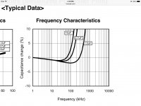
Also, the attenuator I am using has no real effect on linearity since its a much higher impedance than the circuit input itself. There is no change in frequency response or linearity that I have measured, and I did look at this. The attenuator I am using also has left - right trim and a main gain adjust.
http://glass-ware.stores.yahoo.net/baat.html
Mark
I just set the gains of both boards using the 2K pot to 15 DB in unbalanced mode as per the service manual specs. All is working well and sounding excellent!
The interesting thing is my soundstage width and depth are now immense compared to the first set of boards that just had Elna Simlac II caps on the in's and out's. So I will mention to everyone here building this project to skip using Elna's.
Also, the attenuator I am using has no real effect on linearity since its a much higher impedance than the circuit input itself. There is no change in frequency response or linearity that I have measured, and I did look at this. The attenuator I am using also has left - right trim and a main gain adjust.
http://glass-ware.stores.yahoo.net/baat.html
Mark
Last edited:
he interesting thing is my soundstage width and depth are now immense compared to the first set of boards that just had Elna Simlac II caps on the in's and out's. So I will mention to everyone here building this project to skip using Elna's.
Mark
Mark,
Great to hear that the Panasonic caps have worked out so well. I'm very tempted to replace the Black Gates in mine as the 10uF Panasonic should fit on veterans boards without too much drama. I've never been entirely convinced the BG's were better than the Vishay MKT1812's so might be time to revisit.
cheers
Paul
I am building this preamp because I want to eventually have an Aleph J or variant of an aleph J as well as a balanced source. In the past I have experimented with output attenuation in tube buffers in order to utilize the large dynamic range of the tube and maximize the signal to noise ratio. I found it interesting to see this used in the Aleph P as well.
Mark, I have been in the electronics field for over 30 years mostly in laboratory instrument service. I have never heard the term "suitcase header" before. Could you post a part number or a picture of an example when you have a chance.
Thanks
Brian
Mark, I have been in the electronics field for over 30 years mostly in laboratory instrument service. I have never heard the term "suitcase header" before. Could you post a part number or a picture of an example when you have a chance.
Thanks
Brian
I made some observations of the current board DC regulator which seems to run at about 56 volts versus the boards I had been using that were built by Mike W. They actually do put out 60 volts DC. On his boards there is 64 volts present at the gate of Q-23 and with ours there is about 60. There is a 4 volt drop in the mosfet that results in the output voltage. His resistances at the regulator were completely different then what is shown on the Pass schematic and I wanted to get your opinions on it. Perhaps he will see this post.
R-117 Pass 2.21K > Mike W. 1005 ohms
R-118 Pass 4.7K > Mike W. 225 ohms
R-119 Pass 221 > Mike W. 2.4K
Mark
R-117 Pass 2.21K > Mike W. 1005 ohms
R-118 Pass 4.7K > Mike W. 225 ohms
R-119 Pass 221 > Mike W. 2.4K
Mark
Brian...
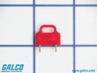
Here are pictures of the suitcase jumpers. The red one is a high end jumper and the others are as used in computers. All are available gold plated. I used the small ones on the DAC I built to place it in the correct mode. Some people call them removable shunts. I call them suitcase jumpers because they some times have that little handle on top.
Mark
Attachments

I made some observations of the current board DC regulator which seems to run at about 56 volts versus the boards I had been using that were built by Mike W. They actually do put out 60 volts DC. On his boards there is 64 volts present at the gate of Q-23 and with ours there is about 60. There is a 4 volt drop in the mosfet that results in the output voltage. His resistances at the regulator were completely different then what is shown on the Pass schematic and I wanted to get your opinions on it. Perhaps he will see this post.
R-117 Pass 2.21K > Mike W. 1005 ohms
R-118 Pass 4.7K > Mike W. 225 ohms
R-119 Pass 221 > Mike W. 2.4K
Mark
Mark
I would go down the chain of Zeners with a voltmeter and record the voltage across them. Although they are nominally 9.1volts it will vary with current and there can be differences in individual parts of up to +-.5volts. If you have one in backwards or one is defective you should be able to find it. The other issue is the current in the Zener string. In the Mike W design he has reduced R117 to get a higher current. This may be because of a lower unregulated input voltage, who knows. If you have 80 volts going in you should have about 9ma or so of Zener current. Double check the value of R117. If you find that all the zeners are running below 9.1v You could decrease the value of R117 to 1K which would double the current. Watch the power dissipation on the series resistor. 20ma x 20volts would be .4w. If you parallel a second 2.21K with the existing one the power dissipated per resistor would stay the same and it's an easy mod to do.
I'm sure it will work fine on 56 volts but it should be possible to bump that up and stay at the design value.
I had 58V on my tested board and already did what Brian suggested here i.e. bumped up the current through the zeners to the nominal 20mA as per datasheet (for mine). it did not help much. I also thought the zener noise would benefit a little from that (unless I got that wrong). I think to get around the zener tolerances stacking up to a lower voltage, the best way is to exchange one zener for a higher nominal value to get the stack back up.
Brian...
Here are pictures of the suitcase jumpers. The red one is a high end jumper and the others are as used in computers. All are available gold plated. I used the small ones on the DAC I built to place it in the correct mode. Some people call them removable shunts. I call them suitcase jumpers because they some times have that little handle on top.
Mark
Thanks Mark, I know what you mean now. I had just not heard the term suitcase jumpers but I can certainly see why you would call them that. I'm doing up a Mouser order right now so I'll add some of those in there.
Koja,
I'm not sure Papa took the drop across the MOSFET into account. Really, 58 volts is fine though. I have 60 volts exactly at the top of my stack. Either add in a 2 volt zener or just stick a 12 volt zener in place of one of the 9.1 volt zeners. That should do the trick.
Mike W changed the component values around the circuit as I pointed out in the post above to arrive at about 64 volts at the gate. This gave exactly 60 volts at the output of the MOSFET. He also has the same stack of zeners we used.
Mark
I'm sure that Papa is taking some numbers pretty deliberatelly - more as range than exact value
for instance - he's always using 36Vct xformers (in FW) production , while always writing +/-24Vdc at PSU
go figure
no need to be anal regarding few volts in 60
for instance - he's always using 36Vct xformers (in FW) production , while always writing +/-24Vdc at PSU
go figure
no need to be anal regarding few volts in 60
It all depends on where your zeners are in the +-.5volt acceptable tolerance from the nominal 9.1volts. At the nominal value you end up with pretty much exactly 60v output. The 60 volts is the nominal value and it could vary by +-4 volts before being out of tolerance considering the parts involved. The good thing is it's easy to fix by swapping out 1 zener to a higher voltage. The other alternative is to just try to fit in an LM783 set for 60volts and get rid of the zener stack all together. With the 783 you could adjust it a bit higher if you wanted, given 80volts or more at the input.
- Home
- Amplifiers
- Pass Labs
- Pass Aleph P 1.7 preamp builders thread