Koja,
If one leaves the relays out do we need to jumper their positions or are they normally out of the circuit and in balanced mode? I would assume they are out but wanted to ask. Since I am all balanced then I will leave them off mine if that's the case.
Mark
If one leaves the relays out do we need to jumper their positions or are they normally out of the circuit and in balanced mode? I would assume they are out but wanted to ask. Since I am all balanced then I will leave them off mine if that's the case.
Mark
Koja... Never mind the relay question!!! I traced the board and I see I have to have the reed relays for selecting attenuation... So in they go.
Mark
Mark
as stated earlier: Hamlin relays are for attenuator switches. Spartans (a.k.a Coto) can be left out if preamp is only used in balanced mode(these are to short the negative input/output to GND).
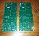
Parts arrived today and some more progress. I am short two 221 ohm resistors which I may have in my parts bins anyway and I still have to solder in the MOSFETS....
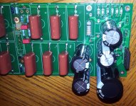
Also, if you order the Nichion FKP2D006801D00JSSD 1000 uf - 100 volt (105c) electrolytics these leads fit the pcb pad holes just fine, and these caps are available from Mouser. No need to enlarge the holes as Koja mentioned but I did have to offset the caps on the board to get them to go down as you can see in the picture.
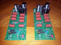
Also, I hope I got the DIP switch oriented correctly. I put switch 1 at the pin 1 mark on the silkscreen....
Mark
Also, if you order the Nichion FKP2D006801D00JSSD 1000 uf - 100 volt (105c) electrolytics these leads fit the pcb pad holes just fine, and these caps are available from Mouser. No need to enlarge the holes as Koja mentioned but I did have to offset the caps on the board to get them to go down as you can see in the picture.
Also, I hope I got the DIP switch oriented correctly. I put switch 1 at the pin 1 mark on the silkscreen....
Mark
Attachments
Last edited:
OK. I received yesterday the matched fets from Brian and stayed up late last night. I stuffed and tested one board.
this is the official ALL CLEAR, the board works as intended🙂.
my only issue was that I have an oversized Xformer driving the regulator fet at high V and I will be screwing the sucker onto the chassis for cooling. my PS zeners also only added up to 58Vreg to supply the preamp. I set the internal gain to 18dB and also checked the three dip switch settings:
min. atten.=max input signal: Switch1 ON, Switch2 OFF: Vgain 18db(balanced)
>>Note: max gain around 21.5dB is available; you may get around 22 with your PS voltage.
both switches (i.e. all input attenuator relays) OFF: Vgain 7.75dB
Switch1 OFF Switch2 ON: Vgain -1.6dB (got AlephP dropping signal because I tuned the internal gain under the max available but turned the max input attenuation ON. I may still change the final settings based on my application).
so this is just to give you an idea before you measure yours.
So my job is finished (except for sending the last few boards), and enjoy your boards!!
Attachments
Last edited:
Great news Koja. The only issue I see for me is soldering the small signal transistors. The pads are really close together. I'll need to switch to a pencil tip and be careful when soldering them. I suggest everyone check for shorts between those pads before powering up. A bit too much solder and you could bridge them. It's easy to do that and not be able to see the problem if you don't have really good light and vision. At 54 my vision is not as good as it was, so I will be extra careful.
yes Brian, those footprints for ZTX450/550 transistors are really small. again: those are standard footprints from the pcb design software library and I am not into the habit of checking and editing those 🙄 (maybe next time I can make them easier to solder). and yes again, I also check those with a voltmeter after soldering. better safe than sorry!
--------------
everybody: please post your pics and comments here once you assembled your APs. looking forward to the new preamps singing around the world 😉.
--------------
everybody: please post your pics and comments here once you assembled your APs. looking forward to the new preamps singing around the world 😉.
Just a reminder to everyone to watch out for static discharge when assembling your boards. I notice that with the cold dry weather now prevalent over much of North America there is a big increase in static discharges. If you have anti static wrist straps wear them to prevent damaging your FETs when handling them. Solder in the protection diodes and other passive components before adding the FETs to the board.
I used 2 wrist straps and grounded metal work surfaces for my testing process. Please use anti static precautions to prevent damage.
I used 2 wrist straps and grounded metal work surfaces for my testing process. Please use anti static precautions to prevent damage.
forgot to note: Mark's DIP switch orientation above is correct. (not that the other orientation would not work; just the switch assignment would be different).
Last edited:
still no pics of even partial builds?  well the guys still waiting for matched fets are excused.
well the guys still waiting for matched fets are excused.
Last edited:
I set the internal gain to 18dB and also checked the three dip switch settings:
min. atten.=max input signal: Switch1 ON, Switch2 OFF: Vgain 18db(balanced)
>>Note: max gain around 21.5dB is available; you may get around 22 with your PS voltage.
both switches (i.e. all input attenuator relays) OFF: Vgain 7.75dB
Switch1 OFF Switch2 ON: Vgain -1.6dB (got AlephP dropping signal because I tuned the internal gain under the max available but turned the max input attenuation ON. I may still change the final settings based on my application).
so this is just to give you an idea before you measure yours.
The P1.7 is designed for an attenuator at the output of the gain stages, and the user manual has a good description of the way it's intended to be used.
The idea is that you run the volume pot as close to maximum as feasible at normal listening levels as this minimises number of resistors - or the amount of resistive material in a conventional pot - in the signal path.
The way to configure is to set the input DIPs to maximum attenuation as a starting point, then adjust the gain pots so you have the the volume pot at close to maximum at the maximum volume you'd normally listen at - take into account CD's with low peak levels when doing this. If the maximum attenuation setting on the DIP's doesn't give you enough volume with the gain pot set to maximum, use the next setting.
I've found with a P1.7 built on Veterans boards, a NPD1 clone balanced DAC and a Hypex UcD180 power amp that I run with the DIP's set to maximum attenuation, the gain pot set to minimum, and still have the Dantimax relay attenuator at -20dB to -30dB the vast majority of the time.
cheers
Paul
yes it sounds like you really needed a passive attenuator since the D amp had enough gain to begin with? I am in a similar situation on my sub channels where I will be using AlephP balanced signal to drive an Icepwr 125ASx2 in mono bridged mode. tons of power and gain, so no real need for help from AlephP. I may even sell that one later and make a Mezmerize instead? I have to try it first though.
as for Papa's concept I believe AlephP is sort of a current source with high output impedance? so the 1kOhm attenuator brings that down and, at the same time, attenuates preamp noise together with the signal. on the other hand this concept leaves AlephP input susceptible to being saturated by hot sources, thus the need for the input attenuator.
originally Papa recommended minimum internal gain setting for just enough volume since in this case the pre noise measured the lowest, but the guys on the forum sort of voted for high gain setting as sounding the best subjectively, so Papa went along with it.
a note: with AlephP the gain suffers if the load impedance drops, another consideration for running AlephP full range into amps with a changing impedance.
a few remarks regarding Dantimax attenuator: I believe its output impedance is 630Ohm for max volume setting and at normal volumes probably 300Ohm? so not very low and the capacitance of long cables after AlephP may cause HF filtering. for me though not a factor at bass frequencies even though I do have very long cables there (5-6m).
another issue with Dantimax RelVol3 boards: channels share the ground and with another star point form a ground loop. I routinely separate these by cutting traces on the board and soldering in a piece of wire. you may want to consider this!
other than that, the idea with AlephP is to distribute attenuation along the chain. I am likely to boost AlephP to up the signal through the long cable, then load it with resistors to ground at amp input, not to saturate it since the amp already has 30dB of Vgain in BTL mode.
another issue with Dantimax RelVol3 boards: channels share the ground and with another star point form a ground loop. I routinely separate these by cutting traces on the board and soldering in a piece of wire. you may want to consider this!
What I found with the RelVol3 // Input2 setup was that removing the ferrite bead between analog and digital sections of the RelVol3 was enough. I also did this on the Input2 boards but I don't think it was entirely necessary. I have the boards hooked up so that everything is grounded back to a star ground and the signal ground points are not used to connect between boards except between the RelVol3 and Input2. This is using veteran's boards of course.
I can probably do without the preamp in the current setup - I have tried running the NPD1 direct into the amp using the digital attenuator in Pure Music to control volume and it sounded pretty good - certainly more transparent than via the P1.7. I've been tempted to try implementing the Pass D1 volume control but not sure it would work in Spencers jfet i/v. Once the Soekris R2R DAC ships I plan on retiring both the NPD1 and P1.7.
Last edited:
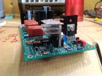
Both my boards work fine. I tested them last night. Can't leave them running very long though as no heatsinks on the matched pairs yet, just on the regulators. I'm making heatsinks today and will post pictures later on.
Mark
Mark
So I have one board heatsinked and its working good EXCEPT my regulator was only giving me 48 volts to the preamp circuit. My raw DC is just shy of 80 volts so that's not the issue. I added one more zenerto the string and that brought it to 58 volts which is very close to optimum. Actually, the IS now 60 volts on the regulator mosfet and accounting for a couple volt drop this is normal. Also, the less voltage the regulator has to drop the cooler it runs. My heatsink's get warm but not hot after a half hour.
Mark
Edit: Fixed regulator problem. One Zener was in reversed. Now I also have ~58 volts.
Mark
Edit: Fixed regulator problem. One Zener was in reversed. Now I also have ~58 volts.
Last edited:
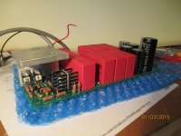
Here are a couple of pictures.... Placing the transistors on both sides of the common heatsink's makes them very sturdy!
Attachments

Last edited:
Another photo which refused to be edited in with the other... Note that I clipped one lower fin off the heat sink to accommodate the vertical pair of resistors... These heatsinks get warm but not hot. I think many builders of this preamp has over heat sinking these things based on images I have seen in other threads. The more sinking you give it the longer it's gonna take to reach thermal equilibrium. Also, note I used thermal pads rather than messy heat sink compound. Assembling the heatsink to the four transistors is a but tricky. When one side is done and tightened up the second side is easier. I also used nylon screws going though the heatsink on the one sinking four transistors. The other screw is going to get changed out for nylon as well. Check each transistor to heatsink for any shorts before you power it up!
Mark
Mark
Attachments
Last edited:
Both my boards work fine. I tested them last night. Can't leave them running very long though as no heatsinks on the matched pairs yet, just on the regulators. I'm making heatsinks today and will post pictures later on.
Mark
If it's built to the Pass schematics you don't really need a heat sink on the matched pairs. I've had mine running un-sinked for 4-5 years without any ill effect.
The originals P17 had all the MOSFETs mounted flat to the board, and only the regulator pass MOSFET's had additional heat sinking. Perhaps diy builders see "class-A" and think it's going to need a heatsink that would cool an Aleph 5?
The regulator MOSFET's definitely need heat sinking.
Last edited:
- Home
- Amplifiers
- Pass Labs
- Pass Aleph P 1.7 preamp builders thread