I have an amp using 3 pairs of darlington per channel (2N6284/87 Motorola, one of the best sounding darlington, TO-3). It is lowly biased looking from the size of the heat sink, which is basically using its casing of 100% Aluminium.
I forget the brand as everything (amp labelling) are in german Incl the parts such as dual jfet from vishay.
Trully Germans did some things like that except other mistakes they did I think the car stereo amplifier i was talking in the past is German made ...
Mistakes like that follow and followed by Giesberts designer that did amplifiers for Elektor that most of them had stabilty issues and after issued there was all shorts of patches to make them Work
This school of electronics never had people enough to produce some innovation.
elektor amplifier around BDW83-84C was made with 1R10W ballast resistors and a VBE multiplier located on the pcb
I expect that most us understand what this might be
The king of thermal runaway considering stability while slower than a locomotive regarding sound ...Add sonic killers at the base of every transistor of 680pf and the catastrophe is done
I expect that most us understand what this might be
The king of thermal runaway considering stability while slower than a locomotive regarding sound ...Add sonic killers at the base of every transistor of 680pf and the catastrophe is done
I have an amp using 3 pairs of darlington per channel (2N6284/87 Motorola, one of the best sounding darlington, TO-3). It is lowly biased looking from the size of the heat sink, which is basically using its casing of 100% Aluminium.
I forget the brand as everything (amp labelling) are in german Incl the parts such as dual jfet from vishay.
I cannot agree with the "one of the best sounding darlington" that you wrote when ft is unknown and the schematic is not available . At least for this transistor one may know the cob to work with and design around ...That is one step ...
I cannot agree with the "one of the best sounding darlington" that you wrote when ft is unknown and the schematic is not available . At least for this transistor one may know the cob to work with and design around ...That is one step ...
Given the circuit and the Cob, you will not be able to tell how it will sound, wont you?
You have your favorite Toshiba BJT for your P3A amplifier. How do you decide that the BJT is one of the best? It is as simple as that. Of course we can find technical reasons for this favorable outcome but it is only a justification for the subjective perception.
Discrete BJT has a lot more competitors and possibilities in a cct than darlingtons. It is then easier to find the best sounding darlington than the best sounding BJT.
I have many darlingtons, unfortunately I have never had a chance to have the famous old Philips darlington in TO220. If you like low Cob, then TO220 is hard to beat. Another one of the best sounding darlington is BD645/646.This is TO220. Another best sounding one is TO240 2SB1560 from Sanken. This last one is easily justified technically as it is a modern one and designed for audio purpose. This one has no internal Rbe resistor on the driver and a perfect Rbe of 70R on the output.
Another best sounding one is TO240 2SB1560 from Sanken. This last one is easily justified technically as it is a modern one and designed for audio purpose. This one has no internal Rbe resistor on the driver and a perfect Rbe of 70R on the output.
Yes - 2SB1560 / 2SD2390 - a very different story.
Great choice for automotive amps, active speakers' plate amps, etc., in my opinion.
I would use them myself for compact applications if I would have access to them - unfortunately, I never did ((
Given the circuit and the Cob, you will not be able to tell how it will sound, wont you?
You have your favorite Toshiba BJT for your P3A amplifier. How do you decide that the BJT is one of the best? It is as simple as that. Of course we can find technical reasons for this favorable outcome but it is only a justification for the subjective perception.
Discrete BJT has a lot more competitors and possibilities in a cct than darlingtons. It is then easier to find the best sounding darlington than the best sounding BJT.
I have many darlingtons, unfortunately I have never had a chance to have the famous old Philips darlington in TO220. If you like low Cob, then TO220 is hard to beat. Another one of the best sounding darlington is BD645/646.This is TO220. Another best sounding one is TO240 2SB1560 from Sanken. This last one is easily justified technically as it is a modern one and designed for audio purpose. This one has no internal Rbe resistor on the driver and a perfect Rbe of 70R on the output.
A designer or repairman when it comes to choice of semis for OPS has 2 jobs to do to start with, there is a third one that comes after .
---I like to call the first job the electrical job meaning : cob , ft, bandwidth, drive ability of previous stages, stress of the previous stages , reactive load tests ,bandwidth tests ,oscillation tests, 4 Ohms tests , current tests , thermal stability, Bias tests for over or under compensation ,distortion tests under many conditions, Heatsink efficiency tests , and finally even abuse tests .
---The second job and given as a fact that with the previous semis you are both happy and safe is the audio job.
There ... choice of bias/semi will effect all the above parameters but also will change slew rate and content of harmonics for the all amplifier.
So before all the electrical tests and before you come to the "sound" test you need first to have the above problems solved and your targets correctly set .
IE one may like/target the sound of low bias, the other may like the sound of high bias as long the thermals are ok with that .
The third think will be to listen to the bloody thing and make sure that your target is achieved according to your taste and safety .
To come up with a selection for my P3A all these have been made starting in 2006 and i cannot tell you that i am finished yet. You see beyond all these you may notice that i made comparison tests between semis and other things so actually you need to multiply this Job by 4 times at least ...Trust me now, It takes time but the result pays back .
One should notice that a simulator is not the tool to work out this job .
At east electronics we managed 1830 audio machines for the year 2016 and for this year front desk computer for reception counts 1124 today and its only May 11 it seems that we will go to 2000 machines by the end of the year .... So please don't talk to me about which transistor sounds good or not we have been listening to them ALL!!!! at any configuration and at any quality, built, make or bias .
Bottom line is that i am going to be the last one to comment on Papa's work and design but statistics have a very different opinion ...
--I don't expect that a job as described above is ever done for AB100
--I don't expect this amplifier to be stable
--I don't expect this amplifier even if finally i am wrong and it is stable to play anything that is audible next to today's standards .
That is only my opinion and originates as described above.
Last edited:
---I like to call the first job the electrical job meaning : cob , ft, bandwidth, drive ability of previous stages, stress of the previous stages , reactive load tests ,bandwidth tests ,oscillation tests, 4 Ohms tests , current tests , thermal stability, Bias tests for over or under compensation ,distortion tests under many conditions, Heatsink efficiency tests , and finally...
There are lots of variables but they are related. When we focus on variables with the least dependencies then the process will be a lot faster. No need bandwidth test. No need oscillation test. Just focus on the selected variables.
Why do you have doubt on NP's work in term of stability? I have designed amps for my favorite darlingtons above only in days and have used them for months or years without stability problem. I have lots of amps, if my designs didnt sound good enough i would have not had used them more than two days.
One should notice that a simulator is not the tool to work out this job
It is my tool. And a tool for several others in this forum. We just have different design protocols.
Why do you have doubt on NP's work in term of stability? I have designed amps for my favorite darlingtons above only in days and have used them for months or years without stability problem. I have lots of amps, if my designs didnt sound good enough i would have not had used them more than two days.
---- All consumer/diy amplifiers based on old darlingtons have a history of fail due to thermal stability and poor SOA .
---- All today's consumer amplifiers based on SAP15 and above family have terrible statistics next to classic methods and now are in end of life status regardless that originally those were supposed to have all these problems solved with bias string diodes to observe temp / bias included and still failed .
----Most of TIP1472-7 amplifiers operate with "patches" miller caps from B -C of the 680pf miller compensation to achieve some stability and still have history of fail .
---This will happen in generic circuits with Just a pair of 142-147 imagine what will happen with 8
---There is no experience or existing circuit of any amplifier capable to operate with 8 darlingtons OPS might be innovative but there is no standard practice around it Tests as described above are in order
---Tip 142 have unknown cob and ft so behavior cannot be predicted it needs to be tested in real life .
---In AB100 there is no miller compensation at all ...That on its own deosn't look right
There is more but less important
Finally as said before you may create a model for tip 142-147 ( dont really know if exists ) multiply it by 8 and give as food to your simulator but your simulator will take for granted that these transistors are totally alike and have equal Vbe and thermal behavior .... That on its own on a device that has a beta of 2000 WILL NEVER HAPPEN...
If you think like that regarding simulation results you are obviously driving in the wrong side of the road
Last edited:
Summer time in Athens
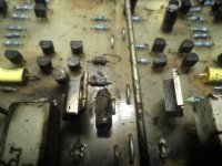
Client got a pair of brand new Harbeth hook them up to NVA amplifier TIP 142-147
Thought that he could keep them on during the day at 0.5W to give the speakers a "burn in "
14 hours later target achieved :
Circuit features a Vbe multiplier located on the PCB though ....
Client got a pair of brand new Harbeth hook them up to NVA amplifier TIP 142-147
Thought that he could keep them on during the day at 0.5W to give the speakers a "burn in "
14 hours later target achieved :
Circuit features a Vbe multiplier located on the PCB though ....
Attachments
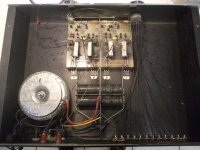
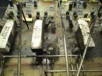
Never reverse engineering in the circuit just what i show on the board schematics are not available Just what i thought i was looking
Th UK angry villager used a fork and a torch to design
one LTP
a current source
A Vas stage with and active opposite
A Vbe multiplier located on the PCB
2 TO92 pre driver
2 TO 220 driver
and OPS that is darlington IE driver and output in the same package
Now how the F**** do you call that ?
EF4 or i lost counting ?
--I don't expect that a job as described above is ever done for AB100
--I don't expect this amplifier to be stable
--I don't expect this amplifier even if finally i am wrong and it is stable to play [/B]
Odd, this amplifier was manufactured by two separate companies for
a number of years, and I didn't hear any complaints.

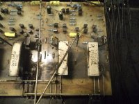
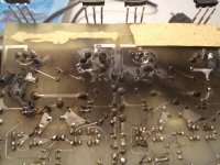
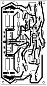
I am preparing the first option for to3 - taking into account the dimensions of enclosure and transistor mounting places.
This still have to be checked - but that is the idea, and there is room for improvement (Unfortunately Iam not pro in pcb design)
base stoppers may be better to solder directly on base pins .
This still have to be checked - but that is the idea, and there is room for improvement (Unfortunately Iam not pro in pcb design)
base stoppers may be better to solder directly on base pins .
Attachments
Last edited:
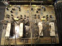
Summer time in Athens
Client got a pair of brand new Harbeth hook them up to NVA amplifier TIP 142-147
Thought that he could keep them on during the day at 0.5W to give the speakers a "burn in "
14 hours later target achieved :
Circuit features a Vbe multiplier located on the PCB though ....
luckily , typical Olde England Audio mist is different from fog surrounding Papa's premises in winter time

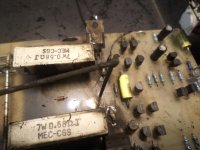
east electronics, I appreciate your knowledge and experience in the audio field, which is definitely more than my, but amplifier on your pics looks bad:no heatsink, no bias transistor on heatsink, transistors glued instead of screwed and i do not see insulation washer between enclosure and transistor- so many mistakes.
The AB100 is an interesting exercise in making do with cheap parts. The TIP140-series darlingtons are cost-effective, but short on SOA, hence the extensive paralleling . The use of the largish emitter resistors should help enforce sharing between output devices.
I'm not particularly keen on building this amp myself, as I chose to use mosfets instead for outputs, with a heatsink-coupled Vgs multiplier. The resulting amp played at the first Burning Amp in San Francisco in 2007. The design was first modeled with darlington outputs, but I only wanted to use a single device per rail. and the TIP140 series darlingtons I had on hand had inadequate SOA. I opted for mosfets instead of searching for heftier darlingtons as I had the mosfets, and was cheap/in a hurry.
For some historical perspective, here's a Motorola app note featuring some audio amplifiers using their newly minted series of integrated power darlington devices.
http://conradhoffman.com/papers_lib/AN483B.pdf
Last edited:
Odd, this amplifier was manufactured by two separate companies for
a number of years, and I didn't hear any complaints.
Dear Nelson
Since the first day of AB 100 my main concern and embarrassment was how to set up my conversation so it doesn't appear like an argument .
I feel too small to have an argument with you .
When you say that this is a commercial amplifier obviously and eventually one will ask which is this amplifier .
Forum has thousands of members one may own one of these amplifiers or if we are lucky a member may repaired one so sharing an opinion about the sound properties or even long term stability should be a bless .
Here is some History
east electronics is an open service operating since 1987. We repair any amplifier you can imagine from pass amplifiers to AKAI from Onkyo till Bryston from Technics to Audiolab anything you can imagine .
We operate in a weird situation with a very weird crowd that has an "audio thingy "
--The average Greek hifier might have 2-3 systems in his house and may also have 2 amplifiers per system.
--Greeks have been sailors ages ago and imported any amplifier you can imagine
--We have collectors that may hold 20 operating amplifiers in their home
--Architects have to deal with clients while having clients want to have in their homes made audiophile corners and design their living room according to the sound system
--Electricians have to deal often with dedicated lines and dedicated grounds for audio
--The average Greek hifier will honor his father's 30 year old sound system with a repair and upgrade
--The average hifier will vaccinate his kids with an audio virus and teach them the difference between a real amplifier and one MP3player
--Athens is a relatively small town but have like 15 PCB small factories operating
--Finally beyond collector's and hifier concept we have due to the economical crises clients that have no money to get a new amp so the repair demands for the old grow huge !!!!
Means that the sample is very healthy and very strong !
To be able to repair successfully such a wide range of equipment there is only one way :
Lear and understand all their dirty little secrets ( yours included dear Nelson ....)
You see ...when you have one amplifier with a toasted output transistor at east electronics we are not done by replacing. We need to know why and we need to know what will it take so this will never happen again .
Often it looks that i am bragging about my numbers Hell yeah i achieved those numbers that way, so yes obviously i am proud of them , and even more proud about bounce rates which are 2% for audio amplifiers and 7-8% for other audio devices .
--sample and hold statistics
--observe pattern failure
--observe epidemic failure
--observe manufacturer mistakes
--observe designer mistakes
--Learn about parts technology and implementation
--Most of all compare implementation of the same circuit or the same part versus fail rates between more than one manufacturer
So if you like to have my statistics about darlington failure Nelson i will publish them for you though it will take some time to collect them .
When one Marantz amplifier that sold 50.000 pcs comes in the lab with a faulty LM317 is one thing , When a Musical Fidelity amplifier that sold 1000 pcs brings in the lab 15 amplifiers with toasted SAP 15 OPS then we have an issue .
When most of NVA amplifiers come in the lab as seen in the pictures above then yes then you have a very serious issue ....
With respect
Sakis
Last edited:
east electronics, I appreciate your knowledge and experience in the audio field, which is definitely more than my, but amplifier on your pics looks bad:no heatsink, no bias transistor on heatsink, transistors glued instead of screwed and i do not see insulation washer between enclosure and transistor- so many mistakes.
That is correct ..this amplifier is made by an angry villager holding a fork and a torch in small Village called UK where they think that :
--Screws in the box effect the sound quality so they use glue for everything
--Glue is also used to hold transistors in the bottom of the case
--An amplifier chassis doesn't need any ventilation the case is sealed and glued
--The bottom plate is enough to cool 2X50W amplifier -
--All countries world wide have and average temp of 21 degrees
--Unknown ft transistors that operate barely in class B is audio quality
--A vbe multiplier has no reason to be installed on any heatsink and operates perfectly by sensing cosmic rays from outer space .
--Mains fuses is a bad bad bad thing and who give a f**k if somebodies home is set on fire
The bad thing is that even more villagers from the same village made similar mistakes Audiolab did it , Musical Fidelity did it ,Magnum did, it NAim did it, Quad did it .... Thermals and bias have been an issue with many UK equipment though in construction/safety errors NVA is a King !!
Last edited:
- Home
- Amplifiers
- Pass Labs
- AB100 Class AB Power Amplifier