ACA standoff and screw size for mounting mosfets to heatsink
Hi, I have the ACA case kit, PCBs but had to source my parts separately as the kit was not available at the time.
How long should the standoffs be for the PCB?
If the screws on mine are too long, can I use a washer underneath the Standoff?
What size screws should I use to mount the mosfets to the heat sink (hole diameter does not seem to be M3)?
Regards, Pieter
I have been using my aca for about a month now and just wanted to say thanks to all involved in making this kit available.
The only hitch I encountered with the kit was that the dc socket did not fit the hole in the chassis so I drilled the holes out a bit.
So far the best speaker synergy I have found is with my Klipsch Heresy II's. These have been sitting my garage for avwhile because no amp I had tried with them before sounded that good to me. I think I will be keeping them in my system for a while.
Sent from my SM-G900P using Tapatalk
I have been using my aca for about a month now and just wanted to say thanks to all involved in making this kit available.
The only hitch I encountered with the kit was that the dc socket did not fit the hole in the chassis so I drilled the holes out a bit.
So far the best speaker synergy I have found is with my Klipsch Heresy II's. These have been sitting my garage for avwhile because no amp I had tried with them before sounded that good to me. I think I will be keeping them in my system for a while.
Sent from my SM-G900P using Tapatalk
When I got my kit a couple of months ago, it had two versions of the DC inlet. The newer one is slightly bigger than the hole provided. The hole fits the original one. I drilled out for the new one also.
And I will second your thanks. I took on the project for fun and to get some taste of the First Watt "sound". I am quite surprised at how good these little guys are. I did move up to a 24v regulated PS which has improved it further.
I have been listening to the ACA monos exclusively for a bit as I sent my single ended pentode tube amp back to the Dennis Had "toy factory" for an upgrade. When that comes back, I plan to rebuild the ACA's with enclosures I will make combining the power supplies and amps in one pair of chassis. I need to use a bigger heat sink due to the 24v PS anyway.
I'll post photos when finished.
Hi all, I'm about to try a 24v power supply on my ACA, been using the 19V laptop supply but everyone says the 24v sounds a lot better.
OK to stick with SMPS for top quality?
This one??
SMPS300RS 24V 230V power supply
Thanks
OK to stick with SMPS for top quality?
This one??
SMPS300RS 24V 230V power supply
Thanks
Hi.I liked ACA amp design very much.All of Pass designs are very good.It is simple and i think will sound great.
As an output capacitor is it good idea to use Vishay Roe EYC series capacitors?I have them on hand.They are rated as 100 volts and low esr.I measured them and they are all around 3000uF.ESR shows 0,00 on Atlas ESR meter.They have a dummy leg and i cut them to use on PCB and it seems ok (dummy leg overlaps on pcb line ) I think it may be good because of these caps have very long life and low esr.And bigger sized caps usually sounds better than smaller ones at same capacity because of they give lower distortion.What is your opinion?
http://www.vishay.com/docs/25138/eyc.pdf
Last edited:
I don't see any issues with J111, J112, BF862.
This is not a very critical part.

Are there any component values that need to change to accommodate a J111/J112 JFET in place of the 2sk170 or is it just a drop in replacement?
We sent a kit to Papa Pass and he wrung it out with his test gear...
Turns out it can be tweaked to have more bias and put out the full SIX watts, with less distortion!
You have to add R15, Value 2.21K
If my board is using BC546, can i add 2.2k resister mod? The specification of BC546 and ZTX450 is slightly different but i don't have electronic background. May anyone help? many thanks
thanks Zen, the temperature isnt that hot like 50C, i can.out my hands on the case without any problem and limit of time.
but i.can feel its hotter than without adding 2.2k
do u guy think it sound better with 2.2k resister mod? it seems better to my ears.slightly more focus. i sometimes afraid its phycho effect.
but i.can feel its hotter than without adding 2.2k
do u guy think it sound better with 2.2k resister mod? it seems better to my ears.slightly more focus. i sometimes afraid its phycho effect.
I have checked the PCB and all the grounds (input signal, output signal, and power) are connected on the PCB as well as the standoff pads. Is there any reason to make all those connections? I'm inclined to run a 14 gauge wire to the power ground and connect that and the others at an adjacent terminal block. Am I missing something?
Thanks
Thanks
ACA Trouble Shooting for a newby please!
Long time audiophile, first time I have ever built something on my own. Minimal practical knowledge, but I can follow instructions and am decent with a soldering iron.
> Built the first ACA, sounds terrific, no problems.
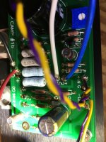
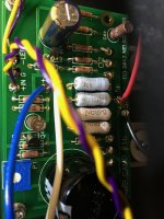
> Built the second, sounds good for 5-10 seconds, then volume drops off a cliff and output becomes very distorted, regardless of source. Gently tapping internal wires or chassis gets a blip of added, staticky distortion.
> Checked all solder joints, everything looks good
> only thing I have found out of order is this: when I test ground and Q1 center pin, DC is 10.2V or so, then takes off to 14, even 15VDC!
Not a clue what to do from here. Any help greatly appreciated.
Long time audiophile, first time I have ever built something on my own. Minimal practical knowledge, but I can follow instructions and am decent with a soldering iron.
> Built the first ACA, sounds terrific, no problems.
> Built the second, sounds good for 5-10 seconds, then volume drops off a cliff and output becomes very distorted, regardless of source. Gently tapping internal wires or chassis gets a blip of added, staticky distortion.
> Checked all solder joints, everything looks good
> only thing I have found out of order is this: when I test ground and Q1 center pin, DC is 10.2V or so, then takes off to 14, even 15VDC!
Not a clue what to do from here. Any help greatly appreciated.
Thanks Zen Mod
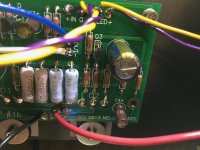
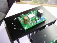
soldering , parts placement and orientation , no contact between mosfet case (center pin!) and heatsink , mosfet properly tightened
Snugged up the MOSFETs (no improvement) and everything else looks good to me.
If these photos don't reveal anything, happy to take more.
soldering , parts placement and orientation , no contact between mosfet case (center pin!) and heatsink , mosfet properly tightened
Snugged up the MOSFETs (no improvement) and everything else looks good to me.
If these photos don't reveal anything, happy to take more.
Attachments
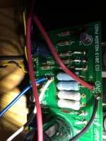
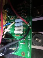
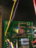
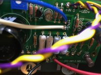
more heat needed
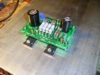
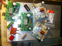
Hi Hemi.
For my soldering i use Ersa Multitip 25W.
The gold plated points needing a bit more time heat up and than the solder you
can see flow/melting and fills the hole and surrounding the wires - double sided board.
Take time- not overheating parts- single point soldering careful.
Hope you can fix all for better result and will work than.
So looks my last soldered board- is tested and worked without trouble.
Attachments
- Home
- Amplifiers
- Pass Labs
- Amp Camp Amp - ACA