Almost any produced in the last 5 years or so, as “super bright” is becoming more and more common. That’s almost certainly what you have in yours, considering your comment about them being like headlights. All you need to do is make the LED resistor more ohms your tame that down.
For front panel "pilot light" applications, I prefer LEDs with the widest possible viewing angle -- which is a manufacturer guaranteed specification on many datasheets. The wider the viewing angle, the greater the likelihood that you'll be able to see whether the LED is on or off, at all positions in the listening room. Not just dead center. Here are a couple example LEDs that specify a quite wide, 120 degree (!!) viewing angle:
3MMLED-GREEN: Jameco Valuepro : LED Super Bright Green Diffused 3mm (T-1) 520nm 5000mcd : Opto & Illumination
3MMLED-BLUE: Jameco Valuepro : LED Super Bright Blue Diffused 3mm (T-1) 465nm 5000mcd : Opto & Illumination
3MMLED-GREEN: Jameco Valuepro : LED Super Bright Green Diffused 3mm (T-1) 520nm 5000mcd : Opto & Illumination
3MMLED-BLUE: Jameco Valuepro : LED Super Bright Blue Diffused 3mm (T-1) 465nm 5000mcd : Opto & Illumination
Wow, what a fun journey this has been! The Pearl 2 is an amazing piece of kit. I just wish I had found this thread sooner, it would have saved me a lot of pain chasing RF (thanks to C7) and trying to balance the output. Almost there now, thanks to the input from all you awesome people. At the tweaking stage now: R14 for gain, and playing with R8 to get the voltage more in line with the ideal around Q3. Have ordered some 20R resistors. Added another 100nF under the board to lower the cut-off. I have fitted 6,800uF caps rather than the specified 10,000uF, as they're shorter, meaning I could fit it all in a low-profile 1U high case. Yes, PSU as well!! and it's as quiet as I've ever heard a phono preamp. Not a hint of hum, even with the volume cranked right up
I'm getting parts ordered for my build. This project is in a queue of many, so I don't expect to build until sometime in the middle of winter. I need to order the chassis, too.
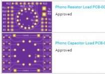
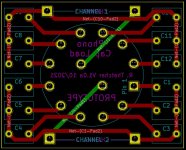
One thing I'm going to play with is the capacitor and resistor loading using rotary switches. My buddy's EAR phono has something like this, so I thought I'd build on that concept. I sent these boards off for fab last night, and the switches are inbound, too. I'll report back on how they work out. If anyone wants to beta test, I'll have extra boards.
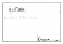
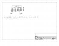
The idea is one switch for caps on a DP6T switch with 5 cap values plus leaving one open for no cap loading.
Resistor loading will be one 16 position switch per channel. All resistors are parallel to the 47k5 on the main board. 15 resistors on the switch + one open position for 47k5 loading.
One thing I'm going to play with is the capacitor and resistor loading using rotary switches. My buddy's EAR phono has something like this, so I thought I'd build on that concept. I sent these boards off for fab last night, and the switches are inbound, too. I'll report back on how they work out. If anyone wants to beta test, I'll have extra boards.
The idea is one switch for caps on a DP6T switch with 5 cap values plus leaving one open for no cap loading.
Resistor loading will be one 16 position switch per channel. All resistors are parallel to the 47k5 on the main board. 15 resistors on the switch + one open position for 47k5 loading.
Attachments
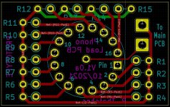
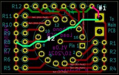
Mark - nice catch! I wasn't thinking to do that at 1AM when I finished... It's easy (and cheap) to throw a few more boards into an existing order, so I added those traces. And while I was at it I made a new wider version with updated resistor footprints. So I'll have vertical and horizontal resistor PCB's to see which I like better...

I'm getting parts ordered for my build. This project is in a queue of many, so I don't expect to build until sometime in the middle of winter. I need to order the chassis, too.
One thing I'm going to play with is the capacitor and resistor loading using rotary switches. My buddy's EAR phono has something like this, so I thought I'd build on that concept. I sent these boards off for fab last night, and the switches are inbound, too. I'll report back on how they work out. If anyone wants to beta test, I'll have extra boards.
The idea is one switch for caps on a DP6T switch with 5 cap values plus leaving one open for no cap loading.
Resistor loading will be one 16 position switch per channel. All resistors are parallel to the 47k5 on the main board. 15 resistors on the switch + one open position for 47k5 loading.
I did this with 5 position rotary switches, and added another one to control gain via R14 to select between 300, 600, and 1K ohms.
I did this with 5 position rotary switches, and added another one to control gain via R14 to select between 300, 600, and 1K ohms.
I'm planning to do a switch for Hi/Lo gain. In reality, it will run on high gain nearly all the time with an MC cart. It may get a little run time with an old beater 'table with a MM - so I'll put the switch in for that case.
I'm planning to do a switch for Hi/Lo gain. In reality, it will run on high gain nearly all the time with an MC cart. It may get a little run time with an old beater 'table with a MM - so I'll put the switch in for that case.
I find that the gain of my Pearl 2 is so high, even with a .2mV LOMC I have to use the low gain setting with a headphone amp.
I need some help from the forum please as I have no Sound from the left channel. Everthing was working fine previously. Red led working, R7 =21V and everything after that =0 V. What should I do next. Thanks
When you say nothing after that, what exactly do you mean? Is there any voltage on either side of R8 or R9? What about on either side of R5?
Cheers
Vic
There is no voltage on either side of R8 or after
I'm no expert, but just looking at the circuit, if you have voltage at R7 and no voltage at R8, then it looks like there's no current flow through Q1 (ZTX450), which could be cooked/faulty. If it is, the only options I can see is replacing it, which is a pain. I'd also check to see that there are no cold solder joints on the Q1 legs. If any joints looks dull or crystalline, try rewetting it with the soldering iron, but don't overcook it.
Lets also wait and see if anyone else with more expertise chimes in.
Cheers
Vic
Thanks, I have a couple of spare ZTX450s so I will try replacing this first. Thanks for your help
No problems. Let us all know how it goes.
If it does work, I'd do a quick check of the voltages to make sure nothing caused Q1's failure.
If you don't already have it, here's a link to a schematic showing some expected voltages (printed on the schematic) and a builders values hand written. The voltages do vary a bit depending on part tolerances, but they should be in the ball park.
Pearl 2 | DIY AUDIO
Cheers
Vic
Hi Vic
Changed Q1 this morning and bingo, everything back to normal. Not sure why it failed after 3 months with nil issues. Thanks for your help.
Andrew
Hi Andrew
Great to hear and pleased to be of help. Parts do fail for whatever reason. I'd still do a quick voltage check just to make sure nothing else is going on (although I'm a bit anal). However, if it all works and sounds good and the magic smoke isn't coming out of anything, then it's usually OK
")
Cheers and good listening.
Vic
Hi all, I am considering building a Pearl 2. As it is a Wayne Colburn design I know I can't go wrong. I have a nice and big enclosure where my dac (DDDAC 1754) and psu for the dac is. It would be cool to have the Pearl in the same enclosure, but I wonder how sensitive it is for other parts in the same enclosure? If I remove the toroid transformer but keep the dac and psu, would that cause issues picking up noice? I know I can just try it out when it´s done, but if the recommendation is to keep it a separate box I will plan for that.
TIA
Chris
TIA
Chris
- Home
- Amplifiers
- Pass Labs
- Building a Pearl 2