Aljordan- the 7800/7900 regulators need 2.5v more input than output voltage to work properly. Anything more will be wasted as heat in the regulator itself. A volt or two extra is no big deal, but many is a bit of a waste.
Berkbear- this is a bipolar supply, you can’t use one of those bricks, you need two. (As mentioned by Codyt) Also make sure they are connected to the same power strip and you switch the pearl on/off at that strip.
6L6-Thank you for sharing your PS built. I started in earnest to review the postings related to the build yesterday. I have ordered the F6 amp build as well and was planning to test the waters with that PSU first and then circling back around to tackling the pearl 2 PS at a later date. However, the more I think about it, the more I may just take a crack now.
I used two motorcycle sized lithium batteries for my +- 36V. Of course it is very quiet.
CentralCoast-Yes, batteries are intriguing. I had a musical surroundings Nova 2 battery powered phono preamp once and the unit was dead quiet. It ran on lithium-ion batteries. I wonder if they make a lithium-ion battery pack(s) with 28V?
I can give a nod for the PSU in the design doc as well. For the first one, I had a bit of an issue thinking about mounting the caps and ended up using large screw mount caps, with point to point wiring to the bridges. The chassis was not huge but larger than I wanted.
For my latest one, I tried to make the case smaller and cost less. I'm using one of the small cap PCB's Pete Millett has on his eBay store with 2 bridge rectifiers. I had the rear panel made in FPE for the IEC, gland and SPST but you can omit the IEC entirely and hard-wire the power cord (so only circular drill is needed).
- Hammond 1455N2202 case
- Antek AS-0522 - 50VA 22V Transformer
- 3x Bridge rectifiers
- Misc -- IEC socket, SPST, cable cinch gland.
- Snap-in caps on a PCB
P.S. Check out Arrow.com for great deals. I've found that they have certain items that are much cheaper than other places, so instead of buying a specific part, I go there and sort by price.
For example, some of these CDE SLPX snap-ins at less than $1 ($3-4 elsewhere), and GBPC3504 for $.60 whereas $3-$4 elsewhere (parts used in this build). Same for C&K SPST toggles.
If I were to do it over once more, I'd design a small PCB for the 2 caps and 8 discrete rectifiers. The PCB cost is cheap.
Attachments
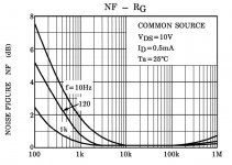
The noise figure vs. source resistance curves for the Toshiba j-fets show increasing noise for >100kOhm signal source resistance.
For increasing the gain of the second stage, does that mean I would be better off decreasing R14 than increasing R15 + R16 (numbers referring to the original schematic) since R16 is already 100kOhm?
For increasing the gain of the second stage, does that mean I would be better off decreasing R14 than increasing R15 + R16 (numbers referring to the original schematic) since R16 is already 100kOhm?
@itsikhefez
I wanted to ask you about how you secured your umbilical. You made that cable, right?
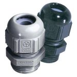
How does the "gland" you've used hold onto the braid and not collapse onto the internal wires? Is there an internal compression ring that grabs the braid?
Is there something similar at the connector end?
I guess I'm just asking, how'd you make that look so neat... and good?
I wanted to ask you about how you secured your umbilical. You made that cable, right?
How does the "gland" you've used hold onto the braid and not collapse onto the internal wires? Is there an internal compression ring that grabs the braid?
Is there something similar at the connector end?
I guess I'm just asking, how'd you make that look so neat... and good?
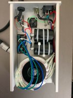
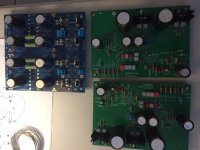
itsikhefez- Great build. Very inspiring.I can give a nod for the PSU in the design doc as well. For the first one, I had a bit of an issue thinking about mounting the caps and ended up using large screw mount caps, with point to point wiring to the bridges. The chassis was not huge but larger than I wanted.
For my latest one, I tried to make the case smaller and cost less. I'm using one of the small cap PCB's Pete Millett has on his eBay store with 2 bridge rectifiers. I had the rear panel made in FPE for the IEC, gland and SPST but you can omit the IEC entirely and hard-wire the power cord (so only circular drill is needed).
- Hammond 1455N2202 case
- Antek AS-0522 - 50VA 22V Transformer
- 3x Bridge rectifiers
- Misc -- IEC socket, SPST, cable cinch gland.
- Snap-in caps on a PCB
P.S. Check out Arrow.com for great deals. I've found that they have certain items that are much cheaper than other places, so instead of buying a specific part, I go there and sort by price.
For example, some of these CDE SLPX snap-ins at less than $1 ($3-4 elsewhere), and GBPC3504 for $.60 whereas $3-$4 elsewhere (parts used in this build). Same for C&K SPST toggles.
If I were to do it over once more, I'd design a small PCB for the 2 caps and 8 discrete rectifiers. The PCB cost is cheap.
@itsikhefez
I wanted to ask you about how you secured your umbilical. You made that cable, right?
How does the "gland" you've used hold onto the braid and not collapse onto the internal wires? Is there an internal compression ring that grabs the braid?
Is there something similar at the connector end?
I guess I'm just asking, how'd you make that look so neat... and good?
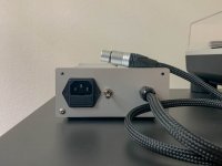
Yea the gland has some form of rubber that compresses as you tighten it. I tighten it until it holds both the braid and the wires. The main purpose (as I see it) is to provide strain relief in case the cable is pulled, to ensure the solder joint (or crimp) at the end of the wire isn't pulled.
The Neutrik connector end has similar strain relief as part of the connector.
Attachments

Don’t forget to Quasimodo CRC snub each bridge rectifier.
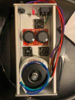
Here's my build of the PS. Can you point me to a schematic for the snubbers?
.... Can you point me to a schematic for the snubbers?
There is an exellent manual about it attached in post 1 here: Quasimodo.
There is an exellent manual about it attached in post 1 here: Quasimodo.
That's a little over my head but thanks.
Oh, sorry about that.......hope this helps:
You will have one of the situations in the left part of figure 13 in the pdf manual at the link. For dual supply (as the Pearl 2) look at first or second schematic from the bottom of the figure. The right side of the figure explains how to test with the Quasimodo jig, forget about that if you don't have the jig.
The test jig for finding optimal values for your transformer is needed, but probably most important is to at least do some damping than nothing. I recall using something in the range of 10nF (capacitor across secondary winding), and 100nF or 150nF in series with 330Ohm. My transformer is with dual 18VAC secondaries, 15VA form Toroidy.
Last edited:
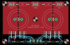
I thought of making this PCB for the Pearl PSU. The width is 98.5mm intended to slide into the Hammond 1455N2202 case and secured with a standoff in the center.
It can alternatively be mounted in a bigger case with the other mount holes.
8x TO-220 rectifiers, 2x 30d snap-in caps with bleeder resistors and CRC snubbers.
Any feedback?
It can alternatively be mounted in a bigger case with the other mount holes.
8x TO-220 rectifiers, 2x 30d snap-in caps with bleeder resistors and CRC snubbers.
Any feedback?
Attachments
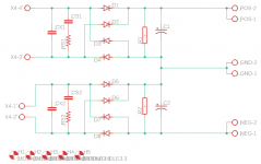
Perhaps if you routed N$1 and N$6 on the red layer instead of the blue, you could double the width of all traces which connect diodes to trafo secondary windings.
Of course there's no need for wide traces to the snubbing components CXn, CSn, RSn since those traces conduct mere milliamps of HF noise, not a dozen amperes of DC.
Of course there's no need for wide traces to the snubbing components CXn, CSn, RSn since those traces conduct mere milliamps of HF noise, not a dozen amperes of DC.
Perhaps if you routed N$1 and N$6 on the red layer instead of the blue, you could double the width of all traces which connect diodes to trafo secondary windings.
Does it matter? The impedance is going to be dominated by the LM7824/7924 regulators.
- Home
- Amplifiers
- Pass Labs
- Building a Pearl 2