")
I'll be revamping the power supply of the Mirror Magic to include a transformer that has separate windings for a boost supply, which should up the capability of the amp to near 100W/channel. That, and tarting up the case with a nice paint job, will make this amp a candidate for this year's Burning Amp.
The paint job and new transformer will wait a while, as other matters (like DC-DC converters for tube amps) have sucked up my time. I did the final tweaking and fixed some bonehead mistakes, then buttoned up the amp as-is. It got its first living room audition last night, and it has authority. It also turns on with no thump, which is nice, because I hate to bodge in things like muting circuits.
The amp still looks pretty good in its bare aluminum Antek case (back when they still had cases with heat sinks), but it would look even nicer with a metallic cast-iron gray finish and a yellow front panel LED pilot.
The amp still looks pretty good in its bare aluminum Antek case (back when they still had cases with heat sinks), but it would look even nicer with a metallic cast-iron gray finish and a yellow front panel LED pilot.
Last edited:
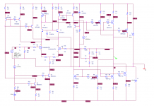
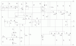
Back around post #40 of this thread, I shared a circuit that included some supplemental current sources to add bias to the input differential amplifier, making the required current swing for full output a smaller percentage of the tail current, lowering distortion by quite a bit. The amp will also require a servo to trim the output offset. I finally got off my behind and laid out boards for both the amp and servo, and they're in process at PCBWAY. As a foretaste of things to come, attached is a sim of the current version of the amp and simmed distortion plot.
Attachments
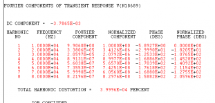
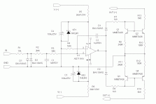
Good catch - I don't know how the sim worked as well as it did with M15 backwards. I re-ran the sim with M15 right side up, and the amount of current for servo correction went way down. I also had to change the value of source resistor on both mirror fets. Rest assured that the corresponding fet on my layout is wired in correctly...
Attachments
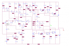
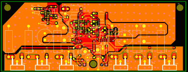
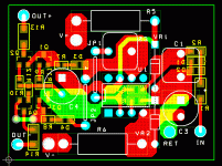
Here's the main and servo boards for the current version of this project. I dropped in a lot of vias to stitch together the power, ground and output top and bottom areas.The servo wil be bodged in place on top of the main board with a number of flying leads.
Attachments

I Got my IRFP9240s today, as well as a healthy population of IRF9610. I will be matching both mirror fets (Q14 and Q18), and hopefully will be able to match a set of the IRFP9240s close to the Vf of the IRFP240s I've already matched. The should mean less work for the servo to attain minimum output offset.
Last edited:
Excited to see your progress @wrenchone . I guess you might integrate the servo on to the amp board at a later stage ?
- Home
- Amplifiers
- Pass Labs
- "Le Mutant" Class A