Hello guys! This is my first post, and I have no real technical understanding of amplifiers 😱
I just bought a used J2. The seller said it was "mint", and that he had only opened the box to check it and take photos.
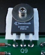
But I took the lid off, and to me it looks suspicious, like as if the original JFETs have been replaced.
They all say SemiSouth E120R100, two of them also say T1026, and the last two say P0939 and T1034.
How bad is it?
I just bought a used J2. The seller said it was "mint", and that he had only opened the box to check it and take photos.
But I took the lid off, and to me it looks suspicious, like as if the original JFETs have been replaced.
They all say SemiSouth E120R100, two of them also say T1026, and the last two say P0939 and T1034.
How bad is it?
if its SJEP120Rxxx it is OK
xxx is whatever - 063, 100, 125
no practical difference
that's "just" series resistance of part when fully opened and one can use any of these in J2 circuit, even mixed
edit: you're scammed ... amp is bad - just send it to OPLDF

xxx is whatever - 063, 100, 125
no practical difference
that's "just" series resistance of part when fully opened and one can use any of these in J2 circuit, even mixed
edit: you're scammed ... amp is bad - just send it to OPLDF
Attachments
Last edited:
Thank you, that makes me feel a lot better!
It wouldn't originally look like this though would it?
Wouldn't it be SJEP120R125 + matching pairs?
It wouldn't originally look like this though would it?
Wouldn't it be SJEP120R125 + matching pairs?

Correction, if it sez R100 you're fine. The other numbers are probably
lot codes or something.
If it sez 063 or 125, those are different parts, not original, but they will work.

lot codes or something.
If it sez 063 or 125, those are different parts, not original, but they will work.
Dear Papa and Zen Mod
Do you mean that R100 can be replaced by R063 without modification of J2 circuit?
I've kept few R063. I hope to use it for Pass diy amp in someday.
Do you mean that R100 can be replaced by R063 without modification of J2 circuit?
I've kept few R063. I hope to use it for Pass diy amp in someday.

I've been playing around with a slightly beefed up J2 topology. I've raised the bias and rails to give 40W into 8ohms at 1% THD (at least according to LTSpice).
The upper MOSFET is now dissipating 62 watts at idle, so it would need some significant heat-sinking. The SemiSouth is running at around 60 watts, which is ever-so-slightly above 1/2 its 115watt max, but I assume still within the bounds of reason?
I also tried paralleling the MOSFET and SemiSouth, but as far as I could figure there's not really enough gain to make use of that. (The topology seems very sensitive to the amount of feedback, so I wasn't able to reduce that.)
I adjusted the opto-coupler's LED resistor so that it starts clipping the gate voltage when THD reaches about 1%. Is that the right thing to do?
I also had to use a 4N25; the 4N35 wouldn't work in my sim. I compared the two datasheets, but got lost. Is the 4N25 suitable here?
(LTSpice file attached.)
Thanks,
Jeff.
Attachments
You could try a cny17-3 in the component library under optos. I think the cny17-3 might be closer to the 4n35 then what you are using in your sim. With the cny17-3 you would have to lower your bias resistors.
Thanks, Rob. The cny17-3 works well with a 270-ohm resistor in R5.
I assume R4 is the bias resistor? I didn't have to modify that to get more-or-less the same response as with the 4N25. The output stage devices are running a couple of watts cooler, so that's no bad thing.
I assume R4 is the bias resistor? I didn't have to modify that to get more-or-less the same response as with the 4N25. The output stage devices are running a couple of watts cooler, so that's no bad thing.
Here's V2.
I studied the optocouplers a bit more and noticed that the CTR decreases as they heat up, so a little more error room is probably in order.
I bumped the optocoupler ballast to 390 ohms. Since it's now what cuts the party short, I was able to lower the quiescent bias back to what I believe is "factory spec" (15K).
Results are a little less power (36W vs 40W), and a little less heat.
Attachments
I would leave R5 at 100 ohms. You can change your bias current to what you wish by changing the resistance values of R10-R13 in your circuit. When all those resistors are equivalent to 0.68 ohms across the input of the optocoupler the transistors will be near 62 watts. Lowering those resistors will increase the wattage and current. Your original optocoupler needed 0.84 ohms to get the same current and wattage as the cny-17 does with 0.68 ohms. The cny17 simulates fairly close to what a 4n35 actually does in a real circuit.
With lower resistance at R10-R13 I had to also lower R4 (or I ran out of room in Class A). However, it all balances out to about the same output, with a hair more dissipation through the output FETs.
I'm not sure I understand the advantage of doing it this way (not that I'm questioning it, just that I'm trying to grok this stuff). Is it because the optocoupler is only involved when things get hairy this way?
Thanks again,
Jeff.
I'm not sure I understand the advantage of doing it this way (not that I'm questioning it, just that I'm trying to grok this stuff). Is it because the optocoupler is only involved when things get hairy this way?
Thanks again,
Jeff.
Attachments
Last edited:
The part of your circuit with the optocoupler is the same circuit described in the burning amp 2015 video by Mr. Pass. Resistor R4 in your amp is a 10k resistor in the baf2015 amp. It might be better to increase c2.
Here's a link to the slides from the talk Rob referred to: BAF Slides Nelson Pass | AudioMaker.
Nelson uses a 1000u cap in the BAF2015 VFET design, which when applied to the J2 topology does smooth out the clipped waveform a bit. However, there's not much difference between 100u and 1000u, so I've changed my sim to use 220u.
Nelson uses a 1000u cap in the BAF2015 VFET design, which when applied to the J2 topology does smooth out the clipped waveform a bit. However, there's not much difference between 100u and 1000u, so I've changed my sim to use 220u.
Even with higher rails, higher bias and more heatsinking, we're still only at 20 watts into 4 ohms. That's probably not going to satisfactorily drive my Maggies in a large room.
So, switching gears, what about a "standard" J2 driving the Maggie tweeter sections and acting as voltage source for an F4 driving the bass/midrange sections?
So, switching gears, what about a "standard" J2 driving the Maggie tweeter sections and acting as voltage source for an F4 driving the bass/midrange sections?
- Home
- Amplifiers
- Pass Labs
- FirstWatt J2