The FW schematic calls for IRFP240's. The Rds(on), gate capacitances, current ratings et al are slightly different, and substitution may alter the operating conditions of the amp.Thanks, looks good, I shall order some irfp250's.
As a tube amp hobbyist I'm going to build my first SS amp and the F3 looks like the perfect start. Some questions on my end due to lack of knowledge on the subject, first on the PSU.
The original PSU calls for 36V power trafo in CRC with 4x0.47R. I got a nice pair of 40V 200W transformers for dual mono and thinking to do CLC with a Lundahl LL2733, 1.7A and more important 3.4 DC resistance.
This should drop the voltage just right but does the additional PSU resistance have any adverse effects?
Here's what I'm thinking, the rectifier diodes will be freds and snubbed.
Attachments
Last edited:

When life give you 40V lemons, make lemonade and throw the excess.
I added a TO220 0.33R input resistor to lower the voltage and current of the trafos a bit, a choke later but for now burning the excess with 4x8ohm parallel resistors, may be good for the coming winter time.

Got an L profile and heatsink glued it for that vertical look. The LUs measure at 1.11 and 1.13, had some 3.9 resistors which should be good.

Let's say I'm crazy and will use the F3 with headphones as well, specifically hifiman HE6 at 84db/mV and 42ohm. Can I get away without feedback? How much will the output impedance increase?
I added a TO220 0.33R input resistor to lower the voltage and current of the trafos a bit, a choke later but for now burning the excess with 4x8ohm parallel resistors, may be good for the coming winter time.
Got an L profile and heatsink glued it for that vertical look. The LUs measure at 1.11 and 1.13, had some 3.9 resistors which should be good.
Let's say I'm crazy and will use the F3 with headphones as well, specifically hifiman HE6 at 84db/mV and 42ohm. Can I get away without feedback? How much will the output impedance increase?
Do I have a bad LU1014D?
After the initial power-up I started to get intermittent static in right channel and drop-outs. Doing a chopstick test I noticed that gently pushing the corner of the board on the jfest side fixed it. Reflowed all solder connection didn't do anything, removing/replacing components including the LU made no difference. When the channel is dead, the 21V goes down to 14V, tugging at the board it goes back to 21V.
Pulled the jfet out and tested it again. I got the expected 1.12V VDS at first but any slight movement/change in the gate pin and VDS with 1ohm and 3V supply jumps anywhere between 0.63V to 2.5V, bench supply current also shows the same current values.
Doesn't look damaged and all the pins are firmly attached.


The very short time I listened to the F3 it sounded fantastic but now it's on the sidelines.
Anyone willing to sell a pair of jfets to get my first SS amp going again?

After the initial power-up I started to get intermittent static in right channel and drop-outs. Doing a chopstick test I noticed that gently pushing the corner of the board on the jfest side fixed it. Reflowed all solder connection didn't do anything, removing/replacing components including the LU made no difference. When the channel is dead, the 21V goes down to 14V, tugging at the board it goes back to 21V.
Pulled the jfet out and tested it again. I got the expected 1.12V VDS at first but any slight movement/change in the gate pin and VDS with 1ohm and 3V supply jumps anywhere between 0.63V to 2.5V, bench supply current also shows the same current values.
Doesn't look damaged and all the pins are firmly attached.
The very short time I listened to the F3 it sounded fantastic but now it's on the sidelines.
Anyone willing to sell a pair of jfets to get my first SS amp going again?
It's a full case from ebay https://tinyurl.com/4vdbbnt8
Arrived flat packed via Fedex after a few weeks and you have to assemble it, not that difficult. Had some light scratches on the inside but outside was perfect, they include the on-off switch and all screws and even front LED. Don't believe them on the one remaining, it was the same when I bought it and one more suddenly popped back. Still, good purchase IMO and seemed to handle the heat of the F3 really well.
Arrived flat packed via Fedex after a few weeks and you have to assemble it, not that difficult. Had some light scratches on the inside but outside was perfect, they include the on-off switch and all screws and even front LED. Don't believe them on the one remaining, it was the same when I bought it and one more suddenly popped back. Still, good purchase IMO and seemed to handle the heat of the F3 really well.
That sounds a lot like when one of my LU1014Ds died- weird rushing static in one channel. I've found that even with dead LU1014Ds one can sometimes read Vgs values in the expected range.Do I have a bad LU1014D?
After the initial power-up I started to get intermittent static in right channel and drop-outs. Doing a chopstick test I noticed that gently pushing the corner of the board on the jfest side fixed it. Reflowed all solder connection didn't do anything, removing/replacing components including the LU made no difference. When the channel is dead, the 21V goes down to 14V, tugging at the board it goes back to 21V.
Pulled the jfet out and tested it again. I got the expected 1.12V VDS at first but any slight movement/change in the gate pin and VDS with 1ohm and 3V supply jumps anywhere between 0.63V to 2.5V, bench supply current also shows the same current values.
Doesn't look damaged and all the pins are firmly attached.
View attachment 1114021 View attachment 1114023
The very short time I listened to the F3 it sounded fantastic but now it's on the sidelines.
Anyone willing to sell a pair of jfets to get my first SS amp going again?
View attachment 1114024
I have a single one I can spare from Papa's recent group buy, but the Vgs value might not match the working one that you have. It shouldn't matter in an F3 as there's only one device per channel, just the operating point, source resistor R5 & hence distortion profile might be slightly different. I'm in the USA so depending where you are, shipping could be de minimis or expensive.
I have a set of Papa’s JFETs.It's a full case from ebay https://tinyurl.com/4vdbbnt8
Arrived flat packed via Fedex after a few weeks and you have to assemble it, not that difficult. Had some light scratches on the inside but outside was perfect, they include the on-off switch and all screws and even front LED. Don't believe them on the one remaining, it was the same when I bought it and one more suddenly popped back. Still, good purchase IMO and seemed to handle the heat of the F3 really well.
Hi guys. I have been given a DIY Tim Rawson built Firstwatt F3 to repair.
Found the fault on the dead channel but I'm somewhat perplexed when it came to measuring the output power and the frequency response.
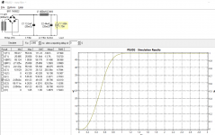
Firstly the output power before there is slight visible distortion on the output waveform is only about 8 watts into 8 ohms. This is consistent across both channels. From what I've read it should be more in the range of 10 - 12 watts. Is this assumption correct? The PSU us using a 330VA transformer which IMHO is more than adequate for the 160W the amplifier draws from the mains. All d.c voltages are correct according the schematic. d.c current drain from the power supply is very close to 1.65A per amplifier which I gather is well in the ballpark.
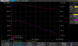
What has me somewhat confused is the frequency response. which has the same slope characteristic on BOTH channels. From 20Hz to 20kHz there's a steady decline in the output of approximately 6dB. This cannot be right, but it's pretty much the same on the other channel. It's like there's some purposefully built in low pass filter? (see the attached Bode plot of the frequency response and phase response.)
Checking the frequency response at the drain of Q1 it's flat.
For reference the signal source impedance is 50 ohms and the amplifier is running into an 8 ohm resistive load.
I've tried adjusting P2 over its entire range to no significant improvement. All adjusting P2 did was affect the gain. I haven't tried adjusting P2 for minimal THD as IMO that's pointless until the frequency response issues are addressed.
If anyone who has actually tested a DIY F3 and can shine some light on what is causing this unusual slope on the frequency response I would most appreciate reading your comments or suggestions.
Found the fault on the dead channel but I'm somewhat perplexed when it came to measuring the output power and the frequency response.
Firstly the output power before there is slight visible distortion on the output waveform is only about 8 watts into 8 ohms. This is consistent across both channels. From what I've read it should be more in the range of 10 - 12 watts. Is this assumption correct? The PSU us using a 330VA transformer which IMHO is more than adequate for the 160W the amplifier draws from the mains. All d.c voltages are correct according the schematic. d.c current drain from the power supply is very close to 1.65A per amplifier which I gather is well in the ballpark.
What has me somewhat confused is the frequency response. which has the same slope characteristic on BOTH channels. From 20Hz to 20kHz there's a steady decline in the output of approximately 6dB. This cannot be right, but it's pretty much the same on the other channel.
It's like there's some purposefully built in low pass filter? (see the attached Bode plot of the frequency response and phase response.)Checking the frequency response at the drain of Q1 it's flat.
For reference the signal source impedance is 50 ohms and the amplifier is running into an 8 ohm resistive load.
I've tried adjusting P2 over its entire range to no significant improvement. All adjusting P2 did was affect the gain. I haven't tried adjusting P2 for minimal THD as IMO that's pointless until the frequency response issues are addressed.
If anyone who has actually tested a DIY F3 and can shine some light on what is causing this unusual slope on the frequency response I would most appreciate reading your comments or suggestions.
Attachments
My last system upgrade (allied to the VFET amp) has left me so satisfied that I spend hours just enjoying the music and have (almost) lost the motivation to build anything.
However, the number of completed amp boards piled on the shelf is quite ridiculous and they need to be tested and cased up if only to make disposal a realistic option. The first candidates are a pair of F3 clone boards by Chas Sample, which I'm actually looking forward to auditioning. And the first puzzle is that the the two unused Jeff Young boards I also have are clearly marked '21V', as opposed to the finished ones marked '+46V DC'.
I'm fairly confident that I'll have used the correct BOM when putting them together, but if anyone can point me to a thread/post explaining the differences and the thinking behind them I'll be able to check components and approach completion with more confidence. It's not so much that I'm lazy (which I probably am) more that some questions simply don't lend themselves to a search engine unless you stumble on exactly the right form of words. TIA
I recently bought a used DIY F3 amp and i just got my acp pre amp up and running so its time to listen to the amp a bit while i was building the acp i had some time to check the F3, so i cleaned up the boards with isopropyl, i removed the aluminium L profiles that attach to the heatsinks, to renew the thermal paste. the aluminum profiles werent perfectly flat, so i sanded them flat to ensure better thermal contact. i also made some copper 'washer's for the fets, maybe it will cool them a bit also. I used thermal paste between the heatsink and keratherm under the fets.


The amp sounds magnificent and is a big step up from my old integrated Chinese tube amp. The acp pre also takes some credits here, cause I briefly used the F3 with an old technics pre amp and while it sounded ok, with the acp it really is another level.
I have measured the usual TP’s when the amp is on for a while and found some mild differences between both channels, and also not exactly the intended values.
TP1:
Left 20.13V
Right 19.33V
TP2:
Left 41V
Right 40.9V
TP3:
Left 1.161V
Right 1.176V
TP4:
Left 3.29V
Right 3.14V
TP5:
Left 7.57V
Right 7.46V
Temperatures of Q3’s are highest at around 55 degrees while the rest of the fets including the Lu1014 is close to 40-45 degrees
The resistors in this build are of original value as in the original schematic.
I measured the TP’s some other time, maybe when the amp was less warmed up and then the differences between channels were a bit more. Especially TP5 was a bigger difference.
I only tried to adjust P1 of the right channel to bring up TP 5, but I noticed it brings up TP3 also so I left it alone for now.
I think the next step would be to try different values for R5 and\or R8?
Would changing R5 from 2R7 to 3R help lowering TP3 while being able to bring up TP5 to 8V with P1 ? Or am I wrong 🧐
And to try and get both channels more balanced I should increase R5 more on the right channel?
Thanks for the help
while i was building the acp i had some time to check the F3, so i cleaned up the boards with isopropyl, i removed the aluminium L profiles that attach to the heatsinks, to renew the thermal paste. the aluminum profiles werent perfectly flat, so i sanded them flat to ensure better thermal contact. i also made some copper 'washer's for the fets, maybe it will cool them a bit also. I used thermal paste between the heatsink and keratherm under the fets. The amp sounds magnificent and is a big step up from my old integrated Chinese tube amp. The acp pre also takes some credits here, cause I briefly used the F3 with an old technics pre amp and while it sounded ok, with the acp it really is another level.
I have measured the usual TP’s when the amp is on for a while and found some mild differences between both channels, and also not exactly the intended values.
TP1:
Left 20.13V
Right 19.33V
TP2:
Left 41V
Right 40.9V
TP3:
Left 1.161V
Right 1.176V
TP4:
Left 3.29V
Right 3.14V
TP5:
Left 7.57V
Right 7.46V
Temperatures of Q3’s are highest at around 55 degrees while the rest of the fets including the Lu1014 is close to 40-45 degrees
The resistors in this build are of original value as in the original schematic.
I measured the TP’s some other time, maybe when the amp was less warmed up and then the differences between channels were a bit more. Especially TP5 was a bigger difference.
I only tried to adjust P1 of the right channel to bring up TP 5, but I noticed it brings up TP3 also so I left it alone for now.
I think the next step would be to try different values for R5 and\or R8?
Would changing R5 from 2R7 to 3R help lowering TP3 while being able to bring up TP5 to 8V with P1 ? Or am I wrong 🧐
And to try and get both channels more balanced I should increase R5 more on the right channel?
Thanks for the help
- Home
- Amplifiers
- Pass Labs
- F3 Builders Thread