udailey, the digikey page you refer to only has voltage regulators
I hope you did order thermisters!
I hope you did order thermisters!
Weird. I copy/pasted from the right page.
PN 317-1256-ND
http://parts.digikey.com/1/parts/953076-thermistor-ntc-1k-ohm-5-mf52a102j3470.html
PN 317-1256-ND
http://parts.digikey.com/1/parts/953076-thermistor-ntc-1k-ohm-5-mf52a102j3470.html
more info on simulations
It seems you're right on the money again Nelson!
I thought about this. Then I checked all my connections and parts
yet again. Then I ran tests again to verify my previous results, but
without any luck. Eventually, I tried some different parts for Q5 and
Q6. I was astonished to find that when I substituted a ZTX750 for
the ZTX550, that the THD measurements for the simulations with and
without the current limiters were in the same ballpark. So I am
assuming that my model of the ZTX550 is somehow FUBAR.
So, to try to add some info for any who are interested, here are some
simulated results for Nelson's F5, using 25V rails. Remember that
I am a novice (although I try to be a careful one), so all of this may
be wrong!
output Z....: 222.961m
input Z......: 101k
transfer fn: 5.713
So the transfer fn is another head scratcher, as I think Nelson said
it is about 15 or so.
Here is some other data. When I say 1.5Vin I mean the input is
plus and minus 1.5V (ie: 3V peak to peak). Also, I think Nelson
considers 2.83V output to be 1W. As an aside topic, I have no
idea why this is. Everything that I have read says that for DC,
W=VI. So while I would bet that Nelson is right and I am wrong,
I have included my W measurements, Also, my first row is for an
output of 2.83V. Also note that the amp starts clipping at around
a 3.7V input.
Feel free to correct anything. I am a newbe.
F5 (standard) 25V Rails
======================
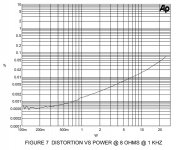
0.5Vin ->~2.83V * 2.6A = 7.4W = 5.2W RMS @ 0.0033% THD
1.5Vin -> 9.0V * 2.6A = 23.4W = 16.5W RMS @ 0.012% THD
2.0Vin -> 12.0V * 2.6A = 31.2W = 22.0W RMS @ 0.0189% THD
2.5Vin -> 14.4V * 2.6A = 37.4W = 26.5W RMS @ 0.029% THD
3.0Vin -> 17.2V * 2.6A = 44.7W = 31.6W RMS @ 0.0428% THD
3.7Vin -> 21.0V * 2.6A = 54.6W = 39.6W RMS @ 0.189% THD
How do the input to output to THD measurements of the simulation
compare to a real unit? The first row seems close. BTW, I am still
building one, but even when I finish, I have no way to measure THD
on a real amp.
Thanks,
Robert
Nelson Pass said:
A lot depends on the quality of models. The Mosfet models are
understood to be the least accurate. I have seen up to 10 to 1
variations in distortion depending on the real Mosfet and the
model.
I have seen simulations from over in the Solid State forum where
a constant Vds JFET yielded pure 2nd harmonic, but on my bench
I have not been able to duplicate that - there is always some 3rd.
I personally do not depend on simulations to predict distortion
in circuits. I prefer to build them and see, although it is also
interesting to compare the results to sims.
BTW, I got about .003% on my first channel, and having built a
few now, it appears that the simple majority of them hit this
without tweaking.
It seems you're right on the money again Nelson!
I thought about this. Then I checked all my connections and parts
yet again. Then I ran tests again to verify my previous results, but
without any luck. Eventually, I tried some different parts for Q5 and
Q6. I was astonished to find that when I substituted a ZTX750 for
the ZTX550, that the THD measurements for the simulations with and
without the current limiters were in the same ballpark. So I am
assuming that my model of the ZTX550 is somehow FUBAR.
So, to try to add some info for any who are interested, here are some
simulated results for Nelson's F5, using 25V rails. Remember that
I am a novice (although I try to be a careful one), so all of this may
be wrong!
output Z....: 222.961m
input Z......: 101k
transfer fn: 5.713
So the transfer fn is another head scratcher, as I think Nelson said
it is about 15 or so.
Here is some other data. When I say 1.5Vin I mean the input is
plus and minus 1.5V (ie: 3V peak to peak). Also, I think Nelson
considers 2.83V output to be 1W. As an aside topic, I have no
idea why this is. Everything that I have read says that for DC,
W=VI. So while I would bet that Nelson is right and I am wrong,
I have included my W measurements, Also, my first row is for an
output of 2.83V. Also note that the amp starts clipping at around
a 3.7V input.
Feel free to correct anything. I am a newbe.
F5 (standard) 25V Rails
======================
0.5Vin ->~2.83V * 2.6A = 7.4W = 5.2W RMS @ 0.0033% THD
1.5Vin -> 9.0V * 2.6A = 23.4W = 16.5W RMS @ 0.012% THD
2.0Vin -> 12.0V * 2.6A = 31.2W = 22.0W RMS @ 0.0189% THD
2.5Vin -> 14.4V * 2.6A = 37.4W = 26.5W RMS @ 0.029% THD
3.0Vin -> 17.2V * 2.6A = 44.7W = 31.6W RMS @ 0.0428% THD
3.7Vin -> 21.0V * 2.6A = 54.6W = 39.6W RMS @ 0.189% THD
How do the input to output to THD measurements of the simulation
compare to a real unit? The first row seems close. BTW, I am still
building one, but even when I finish, I have no way to measure THD
on a real amp.
Thanks,
Robert
Re: more info on simulations
I'm going to assume that is a gain of 5.713 Vout/Vin, since 20log(5.713)=15.13dB, very close to Nelson's 15.3bB.
audiorob said:
So the transfer fn is another head scratcher, as I think Nelson said
it is about 15 or so.
I'm going to assume that is a gain of 5.713 Vout/Vin, since 20log(5.713)=15.13dB, very close to Nelson's 15.3bB.
aside topic
2.83V as 1W.... in 8 Ohm load.
P= Power in Watt
V= Voltage in Volts
I= Current in Amperes
P=V*I=I*I*R=V*V/R
8Ohm load
use P=I*I*R
1W=0.125*8 =>
I*I=0.125 =>
I= sqrt(0.125) =>
I=0.3535.... =>
V=0.3535*8 = 2.8284 nearly 2.83V
2.83V as 1W.... in 8 Ohm load.
P= Power in Watt
V= Voltage in Volts
I= Current in Amperes
P=V*I=I*I*R=V*V/R
8Ohm load
use P=I*I*R
1W=0.125*8 =>
I*I=0.125 =>
I= sqrt(0.125) =>
I=0.3535.... =>
V=0.3535*8 = 2.8284 nearly 2.83V
PANASONIC CAP ?
Hi, Master Nelson.
What's part number of PANASONIC CAP in your F5 from Digikey ?
Thanks
Rubydac
Hi, Master Nelson.
What's part number of PANASONIC CAP in your F5 from Digikey ?
Thanks
Rubydac
Re: aside topic
First, thanks Nelson, jackinn, MEH, and rtirion!
Now let's see if I've learned anything. By the info above, my W figures
are wrong. Using the Vout from the sim, and applying V*V/R where
R=8 we get:
0.5Vin ->~2.83V -> 1.0W @ 0.0033% THD
1.5Vin -> 9.0V -> 10.1W @ 0.012% THD
2.0Vin -> 12.0V -> 18.0W @ 0.0189% THD
2.5Vin -> 14.4V -> 25.9W @ 0.029% THD
3.0Vin -> 17.2V -> 37.0W @ 0.0428% THD
3.7Vin -> 21.0V -> 55.1W @ 0.189% THD
And now solving these for I we get:
0.5Vin ->~2.83V * 0.35A = 1.0W @ 0.0033% THD
1.5Vin -> 9.0V * 1.1A = 10.1W @ 0.012% THD
2.0Vin -> 12.0V * 1.5A = 18.0W @ 0.0189% THD
2.5Vin -> 14.4V * 1.8A = 25.9W @ 0.029% THD
3.0Vin -> 17.2V * 2.2A = 37.0W @ 0.0428% THD
3.7Vin -> 21.0V * 2.6A = 55.1W @ 0.189% THD
So I had a fundamental misunderstanding of how (and how
much) current was going through the speaker?!?! I'm guessing
there is more to this lesson that I need to ponder! This looks
like it might be a start on the road to understanding efficiency
of amplifiers. But that is for another time.
As to the original question of sim vs reality, I can see that we
could have very mixed results due to the models of parts, and
how big one's "ballpark" is. In this case, maybe we would say
the sim is mildly indicitive? Still, this is facinating to me!
Thanks again for all the help!
Robert
rtirion said:2.83V as 1W.... in 8 Ohm load.
P= Power in Watt
V= Voltage in Volts
I= Current in Amperes
P=V*I=I*I*R=V*V/R
8Ohm load
use P=I*I*R
1W=0.125*8 =>
I*I=0.125 =>
I= sqrt(0.125) =>
I=0.3535.... =>
V=0.3535*8 = 2.8284 nearly 2.83V
First, thanks Nelson, jackinn, MEH, and rtirion!
Now let's see if I've learned anything. By the info above, my W figures
are wrong. Using the Vout from the sim, and applying V*V/R where
R=8 we get:
0.5Vin ->~2.83V -> 1.0W @ 0.0033% THD
1.5Vin -> 9.0V -> 10.1W @ 0.012% THD
2.0Vin -> 12.0V -> 18.0W @ 0.0189% THD
2.5Vin -> 14.4V -> 25.9W @ 0.029% THD
3.0Vin -> 17.2V -> 37.0W @ 0.0428% THD
3.7Vin -> 21.0V -> 55.1W @ 0.189% THD
And now solving these for I we get:
0.5Vin ->~2.83V * 0.35A = 1.0W @ 0.0033% THD
1.5Vin -> 9.0V * 1.1A = 10.1W @ 0.012% THD
2.0Vin -> 12.0V * 1.5A = 18.0W @ 0.0189% THD
2.5Vin -> 14.4V * 1.8A = 25.9W @ 0.029% THD
3.0Vin -> 17.2V * 2.2A = 37.0W @ 0.0428% THD
3.7Vin -> 21.0V * 2.6A = 55.1W @ 0.189% THD
So I had a fundamental misunderstanding of how (and how
much) current was going through the speaker?!?! I'm guessing
there is more to this lesson that I need to ponder! This looks
like it might be a start on the road to understanding efficiency
of amplifiers. But that is for another time.
As to the original question of sim vs reality, I can see that we
could have very mixed results due to the models of parts, and
how big one's "ballpark" is. In this case, maybe we would say
the sim is mildly indicitive? Still, this is facinating to me!
Thanks again for all the help!
Robert
Audiorob -- your distortion numbers are high compared to those I experience. If you can, short the inputs and let us know how much noise you see on the output. It should be some tens of microvolts. (NP said 30uV in the article). If you are using a bench supply you might be picking up noise from your power supply leads. If your distortion analyzer has the functionality, switch in the 400Hz high pass filter and see how much garbage you're picking up from the power supply.
Udailey -- I am using the Cantherm thermistors -- they work fine. A little heat shrink tubing on the leads will allay your fears that their leads will come into contact with the power supply or heat sink. You can use a little GE RTV#162 (non-corrosive silicone sealant) or JB Weld 8265 to attach the thermistor to the device or to the heatsink.
To tweak I use the setup in the attachment -- it gives me a range of about 5.5 to 12R -- I start out with 68R//12R = 10.2R, then adjust the pot for 10.2R and lift the ground leg of the 68R. Twiddle the pot until the best THD% is achieved. It's easiest if you can look at the distortion residuals on a spectrum analyzer -- as you twiddle the pot the 2nd and 3rd harmonic relationships change.
I got in a batch of low ohm resistors to see if I could tweak the output resistors -- that's next on the agenda.
Attachments
Thanks Jack. That puts my mind at ease. They just look so frail.
Well, we are off for family camping til late on Sunday. I hope you all have a great weekend and if you are American I hope you have a great Independence Day.
Uriah
Well, we are off for family camping til late on Sunday. I hope you all have a great weekend and if you are American I hope you have a great Independence Day.
Uriah
added stage
In conventional amps there are often emitter follower between inp. & VAS stage. Does Source follower suits for F5?
POS: we can use lots of paralleled OP transistors. As Vds_max=-25V for 2SJ74 is very conservatively stated, we can even raise supply voltage, not much however.
NEG: reduced stability margin. Probably small OP coil makes good and/or RC paralleled with R3, R4.
F5 Power Supply Caps
Hi,
I'm going to stick with the Power Supply in the F5 service manual.
If I replaced the 15,000uF caps with 22,000uF , do I need to change the resistor values (2.2K and 0.47)?
How would I calculated the correct values?
Would I have issues with the F5 driving a Wharfedale 6ohm 90db
speaker?
Thanks.
Hi,
I'm going to stick with the Power Supply in the F5 service manual.
If I replaced the 15,000uF caps with 22,000uF , do I need to change the resistor values (2.2K and 0.47)?
How would I calculated the correct values?
Would I have issues with the F5 driving a Wharfedale 6ohm 90db
speaker?
Thanks.
Re: F5 Power Supply Caps
No need to change anything.
Bengali said:
If I replaced the 15,000uF caps with 22,000uF , do I need to change the resistor values (2.2K and 0.47)?
No need to change anything.
Re: F5 Power Supply Caps
as long you stay in ballpark with PSU voltage , you have no need to change any value in amp itself ; how many uF you have in cap bank - it's up to you and your valet ;
one thing - as you go further increasing caps , it's more important to bypass big caps with several uF of film caps .
wharfs - only your ears will tell ; that really depends of your needs and habits ( usual level , room , etc. )
Bengali said:Hi,
I'm going to stick with the Power Supply in the F5 service manual.
If I replaced the 15,000uF caps with 22,000uF , do I need to change the resistor values (2.2K and 0.47)?
How would I calculated the correct values?
Would I have issues with the F5 driving a Wharfedale 6ohm 90db
speaker?
Thanks.
as long you stay in ballpark with PSU voltage , you have no need to change any value in amp itself ; how many uF you have in cap bank - it's up to you and your valet ;
one thing - as you go further increasing caps , it's more important to bypass big caps with several uF of film caps .
wharfs - only your ears will tell ; that really depends of your needs and habits ( usual level , room , etc. )
Zen,
I am using 12 12,000uf caps. Would you put another cap on each of these or just the last one? Would .22uf PIO cap be alright? I also have some little 1uf aluminum lytics around, or what value would you suggest?
Uriah
I am using 12 12,000uf caps. Would you put another cap on each of these or just the last one? Would .22uf PIO cap be alright? I also have some little 1uf aluminum lytics around, or what value would you suggest?
Uriah
udailey said:Zen,
I am using 12 12,000uf caps. Would you put another cap on each of these or just the last one? Would .22uf PIO cap be alright? I also have some little 1uf aluminum lytics around, or what value would you suggest?
Uriah
say last ones ( from which you're tapping power to pcbs) ;
but more uFs is better - 4u7 , for instance
(hehe , but I can't say that bypassing each of them is harmful
 )
)I will use an avel 35V x2 transformer, 230V tied to the 120V line for half the voltage, 17.5V.
Speaker Output Neg(-) is just a wire from the GND power supply pcb to the speaker jack, this should tie on the last cap?
I've read those CL60 thermistors for inrush can get extremely hot, do they need to be glued to the heatsink?
curious as to why on the F5 PWR Schematic, the CL60 on the primaries are twisted across C9?
THX.
I just got a pair of toroids from John at AnTek www.toroid-transformer.com the AN-4220 which are 400VA 20/20 for $44 each. These are CNC transformers.
It's only a 25 minute drive from my house (he's in N. Arlington NJ which is actually part of Brazil.)
It's only a 25 minute drive from my house (he's in N. Arlington NJ which is actually part of Brazil.)
are you using the F5 power supply or your own?
for 20V, what values for the resistors?
I would go with the single 20V 800VA transformer.
I'm on the West Coast. Shipping probably will be expensive.
thx.
for 20V, what values for the resistors?
I would go with the single 20V 800VA transformer.
I'm on the West Coast. Shipping probably will be expensive.
thx.
Bengali said:are you using the F5 power supply or your own?
for 20V, what values for the resistors?
I would go with the single 20V 800VA transformer.
I'm on the West Coast. Shipping probably will be expensive.
thx.
"Dam*n the torpedoes, full speed ahead!!!!"
There's something called a "Flat Rate Box" from the US Postal Service. You can put 70# in one of these boxes -- that's how John is shipping the toroids. I don't know how long this gift from the U.S. taxpayers will last.
The amp will draw 6A continuous, 10A at peak -- and these transformers are rated for continuous CNC duty so 400VA should be ample. I purchased 2 as I am going to use 4 boards.
- Home
- Amplifiers
- Pass Labs
- F5 power amplifier