Any advice on a good place to look for transformers, power supply parts?
CPC up in Preston from you (aka the cheaper outlet of Farnell stock - not all of it but just right for a hobby)
For instance cpc sell a 2x18v/30VA toroid TX for £15, farnell sell the exact same stock for £27
Just a different business model
That sounds like a plan. I'm going to avoid using Amazon, Ebay now for the main parts. Like opamps, transformers.
Still getting my head round the things like, testing from the negative power rails, and virtual negative rails. I've bought a few books I'm reading...
Good at getting me to sleep, not much else at the moment.
Still getting my head round the things like, testing from the negative power rails, and virtual negative rails. I've bought a few books I'm reading...
Good at getting me to sleep, not much else at the moment.
If i'm doing it correctly, the voltage showing at the gnd is 0.064v @49.9hz. The LED blinks on fades off and the heat sinks get warm. Not much else.
0.064v @49.9hz

Mooly meant , put your black probe on the ground (or virtual ground), set meter to DC volts, then measure with the red probe all the other pins in turn and record them all.
But first you could just try first of all whats the voltage with the black probe on pin 4 and the red on pin 8 , what do you get ?
Then move black probe to ground, and measure off same two pins in turn with red probe.
What do you get?
Little article about all the fake chips flooding the market.
“Gray Market” Floods with Counterfeit Chips Amidst Ongoing Shortage - News
“Gray Market” Floods with Counterfeit Chips Amidst Ongoing Shortage - News
Wow! 75-billion the fake chip market is making.... Its spoiled a lot of things I had planned, and my bloody cmoy is now dead. Even after swooping back to original NE5532.
It’s entirely possible the replacement chip killed something on the board, entirely possible
Please remove the chip, and tell us what voltage pin 4 & 8 have on them
It’s entirely possible the replacement chip killed something on the board, entirely possible
Please remove the chip, and tell us what voltage pin 4 & 8 have on them
So it looks like the chip has possibly taken out the power supply in some way.
We really need all the exact circuit diagrams you used to help troubleshooting if it starts getting heavy... although ultimately it will be an easy fix
")
Please remove the chip, and tell us what voltage pin 4 & 8 have on them
Answer the question
Sorry mike, 1.535v
Wot !?
They are the supply pins to the chip , each (with respect to the ground 0v) should be plus and minus 9v !
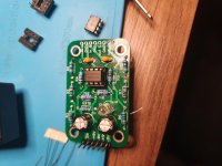
Check the plus and minus 9v is present on the board connector shown in your last pic (on the bottom edge of the board)
Nothing, its showing up as 0.0v. I've tried it with 9v battery, 9v off my supply. Nothing.
Ooops sorry , I only glanced at the pic (I've had a beer
) , it looks like it's fed with a single 9V supply, more than likely not split as a 4.5v/4.5V So if you stick you red and black probes on the incoming 9V and 0v pins on the board you should have obviously 9V and then across pin 4 and 8 you should read 9V , if you want to check if it's a 4.5/4.5 supply set-up check pin 4 (with the black on the 0v pin)
Supply tracks appear to be on the back side of the pcb.... will be very easy to trace back to where continuity is lost as they wind their way to the 9v and 0v board pins, they may go through some current limiting/fusible resistor along the way.
But just get the meter on continuity and follow the tracks back, hold one probe on pin 8 (or 4) and the other testing continuity (power off obviously)
But just get the meter on continuity and follow the tracks back, hold one probe on pin 8 (or 4) and the other testing continuity (power off obviously)
- Home
- Design & Build
- Parts
- Upgrade's didn't work, fake OPA2134?