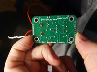
Is the power supply (the pads on the board) configured to allow either 9v or 18 volt operation?
There are only two 'switch' pads which suggest single rail virtual ground to me.
Questions.
1/ Does pin 4 go to the lower left 0V pad? Yes or no.
2/ Do the middle two of that group of four power pads join together? Yes or no.
3/ If the above was 'Yes' then do those two pads connect directly to any other point on the board? Yes or no?
4/ Does the left hand +9v pad (the one next to the switch pad) connect to that switch pad? Yes or no.
5/ If 'yes' above then does the other (left hand) switch pad connect to pin 8? Yes or no.
If the answers are yes, yes, no, yes and yes then it is single rail, virtual ground and it can operate on 9 or 18 volts. For 9 volts you would use the two outer power pads only. The switch pads would need linking (or via a switch).
Can you put a photo up of the back side of the board (in the same orientation as your last photo - i.e. the header at the bottom of pic) so we can see the underside trackage
I'm down in sunny Shropshire today. As soon as I'm back in sunny mancunia I'll be getting straight on it. I'm thinking its the switch that might be the issue.


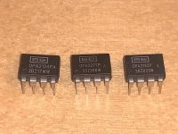
I've been looking at ways to improve the little cmoy I've got. Reading about putting bigger caps to improve bass, metallized polypropylene film caps to improve overall sound quality. So I've done what I thought was the improved upgrades. Now its not working. Unsure why. I changed the NE5532 for the OPA2134PA, this didn't have the usual notch to line up with on the DIP. So I used the circle on the chip as a reference. Unsure if this is correct, or if the chip is the issue.
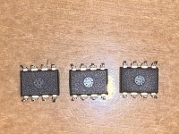
Those look like the fake OPA2134PA that I received. The sanding marks and the somewhat unprofessional fake laser branding.
Plenty of fakes have laser branding now so don't expect the markings to rub off all fakes anymore.
My experience is that power transistors, drivers and op-amps are almost always fake from the usual suspects.
You're right, I'm now only going to use the reputable companies, mouser,rs,digikey and the likes. The extra cost is worth it for the genuine item.
Sometimes a genuine source of parts is already lying around. For example, I scrapped a defunct Onkyo receiver to use the extruded aluminum heatsink, large transformer and chassis for a little project. That left me with boards covered in genuine Toshiba and Sanken transistors along with a good number of usable NJM2068 op-amps.
It costs a little bit but you could get a couple NJM2068, LM4562 and OPA2134 from Mouser and then have fun seeing if you can consistently tell the difference. (Perhaps difficult but potentially fun.)
Also, don't assume that the NE5532 that comes with a kit is a real NE5532. I received plenty of fake NE5532 in kits before I gave up on the usual suspects. One CS4398 DAC came with a fake NE5532...
Last edited:
It should all still work with the original 5532 back in.
You haven't answered any of the questions asked earlier as far as I can see 🙂
Put your meter across pins 4 and 8 of the chip and check you have full supply voltage.
You haven't answered any of the questions asked earlier as far as I can see 🙂
Put your meter across pins 4 and 8 of the chip and check you have full supply voltage.
asuslover, Where did you purchase them from?
I had one of them bad news nights last night, so all my plans ground to a halt.
going to test the voltages now on the pins Mooly.
I'm still learning and a lot of this is new to me, so sorry if I'm getting frustrating. I really appreciate the help, thank you all 🙂
I had one of them bad news nights last night, so all my plans ground to a halt.
going to test the voltages now on the pins Mooly.
I'm still learning and a lot of this is new to me, so sorry if I'm getting frustrating. I really appreciate the help, thank you all 🙂
No problem 🙂
What I would expect you should see is:
1/ The full supply voltage between pins 4 and 8 with pin 8 the more positive of the two.
2/ If you now place the black meter lead on the junction of those two resistors marked R1- and R1+ and measure to all the other pins apart from 4 and 8 you should see zero volts.
3/ Pin 4 measured from here will read negative and be one half of the totla supply voltage.
4/ Pin 8 will now read positive and be one half of the total supply voltage.
I disconnect the switch, it was getting in the way. No voltages are showing up, I have had both and then only one 9V battery connected. Will I need to reconnect the switch, or shouldn't this matter?
Right then Post #42 🙂
Questions... lets see how it is configured.
(I think you need one battery connected between the outer group of four power pins and the two switch pins linked together... but check the configuration)
Questions... lets see how it is configured.
(I think you need one battery connected between the outer group of four power pins and the two switch pins linked together... but check the configuration)
And you see no voltage between 4 and 8 on the socket?
Be logical with the faultfinding.
Begin by putting your meter on the battery negative and checking you really have +9 on the battery positive.
Now move the red meter lead to the +9v pin on the board and check you see +9v.
Measure to the 0V pin and check you see zero volts.
It sounds daft but you have to check the basics first.
If that is OK then look for 9v on the switch pins, both of them as they are linked.
(You still haven't answered the questions in post #42 😉)
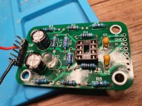
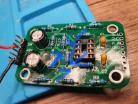
Point of note: if you populated and soldered this up , make sure you flow enough solder to reach through the via’s
You haven’t in these few positions (arrowed)
Fully flowed gives a more reliable connection between sides than just the via and solder on one side.
If it happens to be a dodgy via then the connection between sides isn’t complete, potentially making the circuit not work as intended
You haven’t in these few positions (arrowed)
Fully flowed gives a more reliable connection between sides than just the via and solder on one side.
If it happens to be a dodgy via then the connection between sides isn’t complete, potentially making the circuit not work as intended
Attachments
Last edited:
- Home
- Design & Build
- Parts
- Upgrade's didn't work, fake OPA2134?