As I stated in this thread here they replaced a couple of the ICs with OPA2134 and OPA134s
Restoring & modding a Marantz 3800 | Audiokarma Home Audio Stereo Discussion Forums
Since it seems like the OPA1656 and OPA1641s are drop ins, could this mod in the link above be performed using the 1656 and 1641?
I also grabbed some 100nf X7R and 22pf NPO caps. So the suggestions. Is to put the 100nf caps to the rails, one leg of the cap to the +v and the other leg to the -v pins. The 22pf across the feedback resistors, how can I identify the feedback resistors? Also, does that mean wire them so that the cap is in parallel with each of the resistors?
Dan
Full of conviction I assume the guys at DBX knew very well what they were doing and why they chose the 4558 at which position in their circuitry. Yes, I know of the not-so-good fame of this device. Anyway, there are applications where it simply is hard to outperform it. Last but not least don't forget that we're discussing a FX device here, not a high end reproducer.
Best regards!
"Good' and "low cost" can go together well, "excellent" and "low cost" less so.
If your unit is the original one, the service manual doesn't give a components list to match the schematic. So it's hard to say what opamp to change...
At least 3 4558 are there to drive leds, not a very critical task.
Thanks all, so it sounds like the 4558 isn’t the greatest performer, and yes three are driving the LEDs.
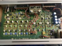
Here are the positions of the ICs.
LF351N: OA5, OA6, OA7, OA8, OA9, OA10, OA11, OA12, OA26, OA27
LF353N: OA1, OA2, OA3, OA4, OA20, OA23, OA24, OA25
RC4558: OA1 (of the LED driver boards) x3, OA15, OA16, OA17, OA18, OA19, OA21, OA22
Hope this helps a little.
Dan
Attachments
On a dual opamp, just put one 22 pF cap across pins 1&2, another across pins 6&7. They will then be in parallel with the feedback resistors and curb any tendency of the opamp to oscillate.The 22pf across the feedback resistors, how can I identify the feedback resistors? Also, does that mean wire them so that the cap is in parallel with each of the resistors? Dan
All the ones in the AUDIO path. Leave others alone.
Oh yes thank you, I figured that. I was hoping someone could help me determine which were in the actual audio path.
Dan
If you really cannot determine that, perhaps you should give this task to someone else with electronics experience.
If you’re not knowledgeable enough to teach, perhaps you shouldn’t be in a forum literally made to share knowledge and to ask questions/request help.
It isn’t rocket science swapping out some ICs and I think that asking for help determining the signal path seems like it would be a fairly common question in this forum, I’ve seen it asked many times. Truthfully your answer seems be from someone that can’t answer themselves.
I don’t know what it is about this forum, most are very excellent. Some of the most helpful folks that love sharing their knowledge. Some know quite a bit, but don’t know it all though like to still help out where they can. I’d like to think I fall in this category, I ask questions and give answers where appropriate. There are those that are still starting out and asking many questions in hopes of retaining what info they can.
And then there are those that post a response to really benefit no party. They don’t give the opportunity to help, teach or learn. Im not sure if it was lack of hugs as a child, too much urine in their cereal, not sure. I’M LITERALLY ASKING FOR HELP DETERMINING THE SIGNAL PATH. If I started a post titled “Need help finding signal path through schematic” I’d get answers. Why clog up the forum multiple threads. If I’m shown I’ll hopefully not have to bother your precious time giving answers like these ever again.
Have you even taken a look at the schematic? I do appreciate the info you offered and the caps to suppress oscillations.
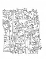
Anyways, thank you to all that have provided me with helpful answers, I absolutely appreciate your help in this! If there is anyone that would be willing to help show me the path that the signal will take id love it. I’ll warn you, the schematic is definitely not the best out there.
Dan
Last edited:
dotneck335 is right though. You could, like most of us started, take the schematic and draw a red line of what you think the signal path is. Then people here can comment and/or correct. That is the necessary "self responsibility" for a learning traject.
Please start with the red pencil. I think it is strange to ask if we can determine that as it is your device, your wish to change it and you should learn how to do stuff. Getting told what to do is not learning but the easy way out which is a weak spot to many tech people. For some reason many of those feel that telling someone what to do is the opposite of helping.
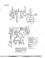
The schematics in post #6 should be attached instead of screen shots as they are very hard to read. Make a new post, click on "go advanced", "manage attachments" etc. Make that either the complete manual or just the schematics. If one wants help one should provide optimal/complete/readable information.
Please start with the red pencil. I think it is strange to ask if we can determine that as it is your device, your wish to change it and you should learn how to do stuff. Getting told what to do is not learning but the easy way out which is a weak spot to many tech people. For some reason many of those feel that telling someone what to do is the opposite of helping.
The schematics in post #6 should be attached instead of screen shots as they are very hard to read. Make a new post, click on "go advanced", "manage attachments" etc. Make that either the complete manual or just the schematics. If one wants help one should provide optimal/complete/readable information.
Last edited:
dotneck335 is right though. You could, like most of us started, take the schematic and draw a red line of what you think the signal path is. Then people here can comment and/or correct. That is the necessary "self responsibility" for a learning traject.
Please start with the red pencil. I think it is strange to ask if we can determine that as it is your device, your wish to change it and you should learn how to do stuff. Getting told what to do is not learning but the easy way out.
The schematics in post #6 should be attached instead of screen shots as they are very hard to read. Make a new post, click on "go advanced", "manage attachments" etc. Make that either the complete manual or just the schematics. If one wants help one should provide optimal/complete/readable information.
He isn’t though. If he gave the answers you just gave it would have been a million times more helpful. People interested in this field though are also new at it post all the time over at audiokarma asking for help fixing their pieces of audio equipment. I’ve helped successfully diagnose hundreds of pieces and repaired them myself in most instances. Should I just start posting “if you don’t know, take it to a tech”. What use is that to those who are interested in learning to do it themselves.
Thank you. I’ll draw out the path I think it’ll take. I’ll report back.
Dan
Here are the schematics in better quality or at least the best I could find.
Frankly, it's too complex for me to say which opamps would benefit from being replaced and I've no experience with such circuits. So I'll leave it to people more experienced.
Frankly, it's too complex for me to say which opamps would benefit from being replaced and I've no experience with such circuits. So I'll leave it to people more experienced.
Attachments
BIG difference between helping and teaching from zero somebody who has no clue.If you’re not knowledgeable enough to teach, perhaps you shouldn’t be in a forum literally made to share knowledge and to ask questions/request help.
This is DIY Audio, not DIY University.
You want the easy answers and throw a tantrum if not pleased.
He *definitely* can find the Audio path, like many others.I think that asking for help determining the signal path seems like it would be a fairly common question in this forum, I’ve seen it asked many times.
Truthfully your answer seems be from someone that can’t answer themselves.
But nobody will waste time on a childish entitled guy.
You HAVE been helped.And then there are those that post a response to really benefit no party. They don’t give the opportunity to help, teach or learn.

Teaching is possible to a point, but a full Electronics course is beyond Forum pssibilties.
So now you turn to INSULTING those who help you.Im not sure if it was lack of hugs as a child, too much urine in their cereal, not sure.
A GREAT way to get help.
You´ll get it if asked in proper and polite way.I’M LITERALLY ASKING FOR HELP DETERMINING THE SIGNAL PATH.
Insulting well intentioned helpers won´t cut much.
Everybody´s time is precious yet nobody´s charging you for it ... as long as it seems to be worth it.If I started a post titled “Need help finding signal path through schematic” I’d get answers. Why clog up the forum multiple threads. If I’m shown I’ll hopefully not have to bother your precious time giving answers like these ever again.
Given your attitude, not so much.
You will get many more bees with honey, than with vinegar.
Well, that is the trigger I also experienced on the reaction to dotneck335 but I was able to suppress it
Let's all be polite again. Please. The schematics as posted by 00940 are hand drawn and small which both contributes them not being easily readable so I will pass this one.
Let's all be polite again. Please. The schematics as posted by 00940 are hand drawn and small which both contributes them not being easily readable so I will pass this one.
Last edited:
- Home
- Design & Build
- Parts
- Which of these ICs can be swapped out with the OPA2134?