I had two 22000 uf industrial(very big) sprague capacitors.Not being used for a decade their value got down to zero ...I couldn't reform it at all...Tried the same thing with some 4700uf that got to 3000uf. No success at all,not 100uf plus after 2 days of trials.Based on what i could achieve ...i don't believe in reforming.
either you did not do it right or the caps were really bad....
when you reform, you are looking at leakage current, 2ma or less after a time,
so i have serious doubts as to why you should quote capacitance values, when those were not the object of reforming.....
FYI, leakage current and not cap value is the object of reforming.....
also, electrolytics are notoriously tolerance challenged, but if you got a very low leakage currents in the micro ampere, then you have a usable cap...
oh, and be sure to discharge your caps after reforming with an incandescent lamp, and short the terminals to prevent accumulated charge if not using right away...
have fun....
forming a belief not based on science is always not a good thing...
What I find quite remarkable about this whole capacitor sound discussion: in 1980 the article "Picking capacitors" by Walter Jung and Richard Marsh was published, see Picking Capacitors - Walter G. Jung and Richard Marsh Although they did write something about nonlinear distortion of tantalum capacitors and of a ceramic class 2 capacitor, the emphasis appeared to be on the effect of dielectric absorption on the waveform coming out of a first-order RC high-pass filter. Dielectric absorption was modelled as a linear effect, using the traditional parallel RC branches.
Then in the 1990's, Cyril Bateman published a series of articles about capacitor harmonic distortion under the misnomer "Capacitor sound", see Cyril Bateman's Capacitor Sound articles | Linear Audio NL Since then no-one seems to care about aberrations in waveforms due to linear effects anymore, and all emphasis is on non-linear effects.
I'm not convinced that either of these effects explains a supposed audible difference between capacitors, as long as the very worst types (ceramic class 2 and tantalum) are kept out of the signal path. The effect of DC blocking capacitor distortion is usually quite small and often negligible compared to other sources of distortion, and the difference in step response between a high-pass filter with a dielectrically absorbing capacitor and one with an ideal capacitor is negligible compared to the difference in step response between an ideal high-pass filter and no filter at all.
the 1980 article started a revolution of sorts....today we are reaping the benefits, film caps that were unheard of prior to the 1980's are now plentiful and widely available....
too bad that polycarbonates are not as widely available, at least on my side of the pond...
It is probably worth appreciating where the paper fits in - the author appears to be the only staff member associated with electronics/audio equipment in a large Uni school of Music. And the technical performance of existing console equipment in that environment would likely be a very small item of interest in the audio recording scope that the associate professor covers. There is also a 'publish or perish' pressure sometimes at a Uni, so I'd imagine the paper and project were a good fit for showing how to set up audio test gear, but not have to be at the bleeding edge of anything and everything contained in the paper, especially as the contents would go over the head of pretty much anyone else in the school.
en fuego audio services
This is basically the gist of the paper. It's not to be generally considered because there's a very specific condition on all of the results:
There's zero DC bias on on all of the capacitors.
Regardless of anything else in the paper, this should be considered as point #1. Without a DC bias, most capacitors will perform fine and this is where electrolytic capacitors can actually be okay (assuming you can live with the DF).
The problem with the paper is only the narrow scope: opamp circuits with zero DC bias and no analysis of passive filter circuits or circuits with significant bias.
Take this paper as it is. It's actually enlightening on where we should concentrate effort and/or cost on part selection.
One of (what I think is) the more useful documents on electrolytics is this thing that used to be on the Panasonic website. I rediscovered it on archive.org, and collected the URLs and titles.
As might be expected, the Audio page in "Major Applications" is the least useful, unless you really need to read those subjective words describing the sound of different capacitor types.
Perhaps the MOST useful part is Use Technique which discusses temperature versus lifetime, and has a formula and nomograph for these.
Panasonic publication "Technical Guide of Aluminum Electrolytic Capacitors"
(Title taken from page 30)
Introduction pp. 1 - 2
https://web.archive.org/web/2012082...sonic.com/www-data/pdf/ABA0000/ABA0000TE1.pdf
Summary of Capacitors pp. 3 - 5
https://web.archive.org/web/2012082...sonic.com/www-data/pdf/ABA0000/ABA0000TE2.pdf
Production of Aluminum Electrolytic Capacitors pp. 6 - 9
https://web.archive.org/web/2012082...sonic.com/www-data/pdf/ABA0000/ABA0000TE3.pdf
4. Reliability of Aluminum Electrolytic Capacitors pp. 10 - 12
https://web.archive.org/web/2012082...sonic.com/www-data/pdf/ABA0000/ABA0000TE4.pdf
5. Use Technique of Aluminum Electrolytic Capacitors
pp. 13 - 25
Wayback Machine
6. Major Applications
pp. 26 - 30
https://web.archive.org/web/2014111...sonic.com/www-data/pdf/ABA0000/ABA0000TE7.pdf
Product System of Aluminum Electrolytic Capacitors
Small can type Aluminum Electrolytic Capacitors
ee27 05 jan. 2012
https://web.archive.org/web/2012082...sonic.com/www-data/pdf/ABA0000/ABA0000TE5.pdf
Agree that's a fair situational takeaway. Also caught the note about not reading too much into the precision of this test. Understanding the mechanisms at play when the test circuit is under duress - +16 and +20 - might still have value as the distortion differences even masked by the 5532 contribution seemed significant. Not sure the author intended 20% precision.
What I understand from the article is that the excessive distortion levels at +16 dBu and +20 dBu are simply due to op-amp clipping. Apparently they clip a bit harder with capacitors than without them, which seems reasonable as high-pass filters can have overshoots.
forming a belief not based on science is always not a good thing...
Billions of people worldwide might not agree with this

The links I posted are to a different version of the capacitor thing I had gotten so many years ago. Here's a link with the coveted audio info.
Wayback Machine
Wayback Machine
So you have a good possibility to do this everything and fill a gap.What?? All this guy did is to measure distortion??? No square wave, no ripple test nothing?? Not even frequency response?? Temperature etc.... How does it affect the capacitor??? How about run-in?? After 100hrs of run-in, any changes?? Charging rate, discharging rate?? Nothing.....
And then, no citations, no references nothing......You call this paper???
As for me - I want to thank the author (authors ?), and to C. Bateman, and to others who do something to 'shed a light' to the mysterious world of capacitors sound.
And an absence of a result is a result too.
Last edited:
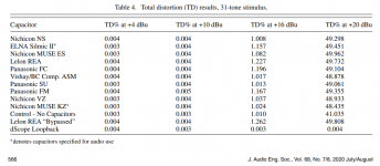
From the last table (Table 4) and from previous pictures in the article where all caps have almost the same THD (+-50%) I can see that author is still far from real capacitor distortion. I would rather say that his measuring installation is not good for this (and he has the wrong result). He definitely missed something. Possibly he has to more thoroughly read the Cyrill Bateman's article?
Anyway, this is still better than nothing.

Anyway, this is still better than nothing.
Attachments
Last edited:
TD at +4dBu is at the loopback level so nothing to see here.
TD at +10dBu is almost at the loopback level so nothing to see here too.
TD at +16dBu shows the same 1% value (+-10-20%) for all caps - so that means for me that it is nothing to see here. I am sure real caps can't be the same.
TD at +20dBu shows strong clipping so nothing to see here. (This means that we possibly were few dB somewhere near clipping at +16dBu too).

That means for me that his measurement installation doesn't have resolution enough at +4...+10dBu. And it just distorts at +16..+20dBu.
TD at +10dBu is almost at the loopback level so nothing to see here too.
TD at +16dBu shows the same 1% value (+-10-20%) for all caps - so that means for me that it is nothing to see here. I am sure real caps can't be the same.
TD at +20dBu shows strong clipping so nothing to see here. (This means that we possibly were few dB somewhere near clipping at +16dBu too).
That means for me that his measurement installation doesn't have resolution enough at +4...+10dBu. And it just distorts at +16..+20dBu.
Last edited:
For those who can not read the article:
Prof Anderson is a practical gear-tech working between "real" studios and academia. (Typically, neither one is a real job.) By budget and preference, consoles from the 1980s are often used, but often need re-capping.
"....exploring options for replacing interstage coupling capacitors in an analog mixing console from the early 1980s. Upon examining options for suitable replacement capacitors, it quickly became clear that there are as many opinions ............. There is, however, a dearth of empirical data ..........."
The question arises: "use the $3 caps or the $0.10 caps?"
Since a large console has 100+ large caps in the nominal signal path, and cap-jobs are necessary but not sexy like goldtone microphones or silk spit-screens, he wanted to know of any *measurable* difference justifying $300 vs $10.
Also, this is "get it working like new". Re-consideration of opamps and bias/loading resistances is moot because they like the old-time sound AND the budget is very finite.
While there are more tests which could be run, THD (vs Frequency!) is a traditional first-cut for problems, and 30+tone tests can be a fine-tooth comb for IM troubles anywhere in the frequency band.
The gross-overload runs are forbidden in home hi-fi(?) but relevant to studio mixer, especially around enthused players or/and student engineers. "Overs" WILL happen. Does one cap "splattt" more than another? The difference of caps is about nil. No-cap is different but so little that we favor caps over pot-scratch. He does on run with an alternative op-amp, which does show a graph-difference in the top octaves. Opamp rolling would be a different paper and budget.
Geez guys, the author is just categorising if capacitor choice affects the distortion in the generic line-stage equipment that he comes across in recording studios. I'm sure he has got better things to do than go down a rabbit hole of further experimental setups, or trying to repeat others experiments.
What is the right result?(and he has the wrong result)
Geez guys, the author is just categorizing if capacitor choice affects the distortion in the generic line-stage equipment that he comes across in recording studios.
Not necessarily all distortion, though. IIUC, stationary harmonic distortion was measured. A good start, at least.
Seems to me if capacitors sound different to multiple skilled listeners, then chances are reasonably good that other types of distortion should also be evaluated. Linear distortions, memory effect hysteretic distortions, etc.
The point is to keep looking until some cause, or causes, of audible differences can be identified.
- Status
- This old topic is closed. If you want to reopen this topic, contact a moderator using the "Report Post" button.
- Home
- Design & Build
- Parts
- AES: Evaluating Electrolytic Capacitors Specified for Audio Use