In the 31 tone test the author concludes:
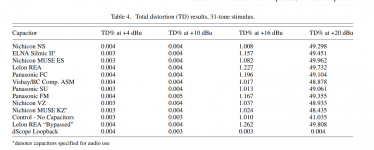
Results of all tests at +4 dBu and +10 dBu show no appreciable increase in distortion products over the test instrument. At +16 dBu, we begin to see slight differences between capacitors, but still no more than a 0.25% increase in distortion over the control.
The Lelon REA's 1.227% is a 22% increase over the Nichicon NS at 1.008%. All the caps appear to soil the sheets at high levels, showing distortion nearly 20% over the 'no-cap' control circuit. The takeaway may be don't use electros or 5532s.
Still all credit to Anderson, that must have been a ton of work.
i have no problem with people posting anecdotes, after all that was their experience, but to push other people to embrace their beliefs, that will be something else....
laws of physics are inviolable....
laws of physics are inviolable....
rdf, I think the 31 tone test results need a bit more appreciation before any broad-brush difference can be assumed due to particular capacitors.
The author did indicate that one DUT with capacitors gave a slightly lower TD than the control channel without caps, and indicated there may be noticeable TD differences between channels due to gain and resolution issues. That could raise a red flag as to cherry picking a performance difference, especially when all DUT channels gave pretty much the same TD results at 6dB lower level, and 4dB higher level, and where opamp distortion was pretty much the major TD instigator.
I reckon the takeaway is that this is what to expect with 5532AP based line-level mixing desk audio equipment - and that may well be good general information for JAES readers. Maybe some of those readers will also check out whether they can swap out their 5532 devices for LME49720s, although at $3 a pop that may cause the thought bubble to burst.
31 tones suggest a lowest frequency of 20 Hz and highest of 20 kHz with the frequencies in between in 100-125-160-200-250-315-400-500-630-800 steps. I recall it sounded weird.
It is more subtle. A multitone has the frequencies spaced such that their distortion products remain separated. That is necessary to be able to find back the individual harmonics and IMD products from each test frequency.
AP has a utility to calculate the frequencies, and the frequency values look almost random (but they are not) like 104.6Hz and 11.45kHz. There is also an ISO standard multitone signal that has all these frequencies.
Then there is the phase between the signals which is also very precisely calculated to keep the crest factor under control.
In other words, designing a good multitone test signal has more to do with math than with audio.
Jan
For those who don't believe break-in is necessary, someone from our forum has shown it to us using an oscilloscope.
Capacitor Burn-In/Break-In
This is also why I stress that testing brand new capacitors are pointless.
That is not a capacitor test, it only shows the stuff on the mains voltage, and yes, that changes from time to time. Anecdotes.
I find it interesting that you dismiss a test that at least has some scientific value, and agree to something that is pretty much BS.
Not a good way to increase your knowledge ;-)
Jan
Last edited:
There is a process called capacitor reforming. It happens with electrolytics that have been unpowered for a long time. When powered again, the electrolytic in the cap have to 'form' again, a chemical process, before the capacitance is back to the original value. It can be observed by measuring the leakage current through the elcap; that starts out high when powered again after a long time of inactivity, and then drops to a low value over the course of minutes or sometimes an hour.
Has nothing to do with distortion or 'burn in'.
Jan
Has nothing to do with distortion or 'burn in'.
Jan
cap reforming is a different ball of wax....very useful before using caps that have overstayed the shelves for too long a time...
I had two 22000 uf industrial(very big) sprague capacitors.Not being used for a decade their value got down to zero ...I couldn't reform it at all...Tried the same thing with some 4700uf that got to 3000uf. No success at all,not 100uf plus after 2 days of trials.Based on what i could achieve ...i don't believe in reforming.
That is not a capacitor test, it only shows the stuff on the mains voltage, and yes, that changes from time to time. Anecdotes.
I find it interesting that you dismiss a test that at least has some scientific value, and agree to something that is pretty much BS.
Not a good way to increase your knowledge ;-)
Jan
Dismiss the test that dosnt back up your delusions.
What I find quite remarkable about this whole capacitor sound discussion: in 1980 the article "Picking capacitors" by Walter Jung and Richard Marsh was published, see Picking Capacitors - Walter G. Jung and Richard Marsh Although they did write something about nonlinear distortion of tantalum capacitors and of a ceramic class 2 capacitor, the emphasis appeared to be on the effect of dielectric absorption on the waveform coming out of a first-order RC high-pass filter. Dielectric absorption was modelled as a linear effect, using the traditional parallel RC branches.
Then in the 1990's, Cyril Bateman published a series of articles about capacitor harmonic distortion under the misnomer "Capacitor sound", see Cyril Bateman's Capacitor Sound articles | Linear Audio NL Since then no-one seems to care about aberrations in waveforms due to linear effects anymore, and all emphasis is on non-linear effects.
I'm not convinced that either of these effects explains a supposed audible difference between capacitors, as long as the very worst types (ceramic class 2 and tantalum) are kept out of the signal path. The effect of DC blocking capacitor distortion is usually quite small and often negligible compared to other sources of distortion, and the difference in step response between a high-pass filter with a dielectrically absorbing capacitor and one with an ideal capacitor is negligible compared to the difference in step response between an ideal high-pass filter and no filter at all.
..the takeaway is that this is what to expect with 5532AP based line-level mixing desk audio equipment..
Agree that's a fair situational takeaway. Also caught the note about not reading too much into the precision of this test. Understanding the mechanisms at play when the test circuit is under duress - +16 and +20 - might still have value as the distortion differences even masked by the 5532 contribution seemed significant. Not sure the author intended 20% precision.
It is probably worth appreciating where the paper fits in - the author appears to be the only staff member associated with electronics/audio equipment in a large Uni school of Music. And the technical performance of existing console equipment in that environment would likely be a very small item of interest in the audio recording scope that the associate professor covers. There is also a 'publish or perish' pressure sometimes at a Uni, so I'd imagine the paper and project were a good fit for showing how to set up audio test gear, but not have to be at the bleeding edge of anything and everything contained in the paper, especially as the contents would go over the head of pretty much anyone else in the school.
en fuego audio services
en fuego audio services
Last edited:
- Home
- Design & Build
- Parts
- AES: Evaluating Electrolytic Capacitors Specified for Audio Use