Certainly, usig a tweeter with more limited verticals, the dispersion will better match the array’s.
iirc, ak used a ribbon with his Needles with 16(?) W3-871. They sounded decent. Losing he 871’s top end colouratiins really cleaned things up, and, at least on the short listen i had, did not suffer the discontinuity issues that one would expect.
dave
iirc, ak used a ribbon with his Needles with 16(?) W3-871. They sounded decent. Losing he 871’s top end colouratiins really cleaned things up, and, at least on the short listen i had, did not suffer the discontinuity issues that one would expect.
dave
The vertical dispersion changes with frequency. If the wrong point is chosen then only the lower treble will be exposed to the reflection, which I don't feel is a good compromise.Certainly, usig a tweeter with more limited verticals, the dispersion will better match the array’s.
Thank You
To all who've generously given their time and expertise on the forum, It is truly appreciated.
HAPPY THANKSGIVING!
To all who've generously given their time and expertise on the forum, It is truly appreciated.
HAPPY THANKSGIVING!
Oh....
Sorry- I'm a bit confused. While I do get the part about crossing over above where problematic room reflections occur. But if the tweeter is supposed to "beam" in the vertical direction, and will be rolling off below 3kHz at 18dB/octave, why are we
so concerned with the ceiling, which is more than four feet away? Is it because it's the nearest highly reflective room surface?
Thanks.
Hmm, with little time available and not recalling any of JG's LA doc ATM, my 'knee jerk' response is to point out that an 'infinite' line need not be room height, just ~71% of it and that one can easily get a 'close enough' F-6 dB beaming frequency with this simple math:
F-6 dB = 10^6/[wall angle*mouth width]
Example: 10" wide flat baffle x 60" height suspended in 4 pi space = 10^6/[180 deg*10"] = 555.56 Hz horizontal
10^6/[180 deg*60"] = 92.59 Hz vertical
2pi space mirror's the speaker's area/shape assuming it's perpendicular, so these frequencies will in theory be a 1/2 octave lower [0.7071x].
Floor, ceiling bounce: SBIR calculator
...
12 drivers/array.
2+tweeter as an MTM...8 or 10 as woofers... potential to get things together in a way that allows a 2.5way.
dave
Hi Dave. Hope you had a nice Holiday.
Now comparing different tweeters for use in Mtm.
For 8, 9, or 10 woofers, would you recommend even series/parallel or tapered attenuation towards the Mids? I understand that first option adds a few more dB.
Also, how would you recommend we make it 2.5 way (i.e. use a baffle step L//R filter, multiple low-pass driver frequencies, or cross all woofers to Mids at the baffle-step frequency)?
Thanks
Last edited:
Our thanksgiving was a month ago :^)
I did get soaking wet in the monsoon rains.
With that many drivers there are many ways to wire, i would not shade, and if going 2.5 way work it so one gets less thahow much lift.
dave
I did get soaking wet in the monsoon rains.
With that many drivers there are many ways to wire, i would not shade, and if going 2.5 way work it so one gets less thahow much lift.
dave
Quote"Our thanksgiving was a month ago :"
Oh! Canada...thanks for responding.
Quote:"
With that many drivers there are many ways to wire, i would not shade, and if going 2.5 way work it so one gets less thahow much lift."
😕
Is it just me, or did we lose part of your sentence?
I'm anxious to learn ways to wire the lower drivers. Plus,
for example if 8 drivers are in regular series parallel, we get 4 ohms,while 9 drivers wired as 3 series sets of 3 in parallel gives 8 ohms. Which configuration would be preferred to provide the right level for baffle-step correction using the crossover alone?
Thanks
Last edited:
You could vary this with frequency.there are only two valid options at the floor. Full output or none.
If you put the drivers that are in the sections to the left in the diagram on the back of the box (or sides or top) or connect with a series L to roll off the top.
Either way it gives you a full 6dB of lift. I’d have to give some thot to losing less. Might need to lose a pair of drivers/side.
Wait, let me think about that.
If the MTM is 4Ω and if we wire the 8 for 16Ω then it puts out 6 dB more due to number of drivers, less 6 dB for the impedance. No BSC. But lots moref room for EQ.
Too late to do more gymnastics…
dave
If the MTM is 4Ω and if we wire the 8 for 16Ω then it puts out 6 dB more due to number of drivers, less 6 dB for the impedance. No BSC. But lots moref room for EQ.
Too late to do more gymnastics…
dave
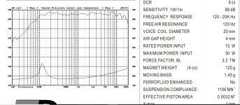
Tang Band W3-665sc is rated at 6ohms DCR,
8 Ohms nominal impedance. My drivers average 6.1-6.15 DCR on my B&H precision meter (8.2ohms?)
The rated sensitivity is 88dB/W/M, but their graph shows it between 84-86dB in the area below my 650-750hz(depending on final baffle width) low-pass filter. Note the slight LF rise as we approach our 150hz box cutoff (my sub cubes go up to 160Hz, 2nd order).
Attachments
Last edited:
I said i would not shade, not intentiallt, but the use of 3 drivers, does introduce shading by definition but this is position dependent thing and here you would use it to try to get impedances and driver output somewhere between 1 and 6 dB BSC.
dave
dave
Ok,
I'm confused, and couldn't find this in Google.
How does the use of 3 drivers introduce shading(versus 2+2//2+2 series parallel)?
Getting "driver output between 1 and 6 BSC"-
That's quite a range.. How do you determine that?
To reiterate, I'm using free standing 5ft. monopole line towers about four feet from the rear wall, and about six feet from the sdewalls.
Thanks
Last edited:
BSC theory, design; hopefully this will be sufficiently helpful enough to adapt it to whatever you're trying to do:
Baffle Step Compensation
General Speaker Related Articles
Baffle Step Compensation
General Speaker Related Articles
Thanks for the links. I'm reading the articles, but am already familiar with the work by Elliott. The one on the variable baffle-step circuit was interesting.
l'm still hoping someone who reads here has done something similar, and could share, so I can avoid unnecessary "cut and try" experimentation. Looks like I'll keep searching and try another forum...
Thanks for your time.
-Charles
l'm still hoping someone who reads here has done something similar, and could share, so I can avoid unnecessary "cut and try" experimentation. Looks like I'll keep searching and try another forum...
Thanks for your time.
-Charles
Dave!
Sorry to be a pain butt-
Quote:"...I would not shade, not intentialy, but the use of 3 drivers, does introduce shading by definition but this is position dependent thing and here you would use it to try to get impedances and driver output somewhere between 1 and 6 dB BSC."
I have read a bunch, but still can't figure out what you mean(I'd originally mentioned 3x3 drivers):
If I use 9 of the W3 8ohm drivers, 3 paralleled sets of 3-in-series, I still get 8 Ohms, right? But-
HOW does that "introduce shading by definition"?
(Jim Griffin shows unequal groups give shading).
My driver line is within 3 feet of the floor, 4 feet from rear wall, 5.5 feet from ceiling, 6 feet from side walls, and.9 feet from the listening seat (all approx.).
Thanks.
-Charles
Last edited:
9 driver sis the suare of 3 so series/parallel brings you back to the nominal impedance of one driver.
If you have just 3, andm assuming nominal 8Ω, they are not all in parallel (2Ω) or series (24Ω) if you wire the drivers in series. Any other arrangment has 2 in series paralleled with a single driver. Series is best suited from 4Ω drivers, parallel with 16Ω drivers.
This gives a nominal 6Ω, but the 2 drivers in series, taken together, have about the same outut as the single driver. Put all 3 on front, and wire the outer ones in series and the outer drivers are shaded 3 dB down form the main driver.
dave
From a prosound POV: the fact that there's '3 paralleled sets of 3-in-series', i.e. unless everything is identical, each segment will in theory have a slightly different 'tone' or worse, unbalanced power sharing where one section can potentially 'hog' most of the available current with all the downsides this implies.
Last edited:
An issue which in practise is not a big issue, but if you want to be annal you would measure all the drivers and match in sets of 3 that give the closest sensitivity match.
dave
dave
- Home
- Loudspeakers
- Multi-Way
- Help Converting Line array into multi-way system?