I get one idea but not sure how to implement.
How difficult can be to design meta-material type of addition to existing tweeter and beams so it really will improve tweeter response? 3D printing is not problem but rest?
How difficult can be to design meta-material type of addition to existing tweeter and beams so it really will improve tweeter response? 3D printing is not problem but rest?
Since the structure is already fabricated, it should be easy to apply the pipe insulation foam section to the rear beam ... it should just slip on. The foam will be reflective. If, instead, you're looking to kill some of the rearward response, you'd be wrapping that support beam with felt.
The angled sides @ the front of the amt, as they are now, will introduce local diffraction characteristics. The edges are sharp. If the amt beams at a certain frequency range the sharp edges become less of an issue. It's the amt lower frequency range, were it hands off to the mids, that the diffraction effects increase and upset the polar response.
I'd slice a section of pipe insulation in half lengthwise and tape each half pipe to the outer edge of the angled beams at the front. The half round will smooth the response and work to kill diffraction. It should also lower the amt frequency response because the added pipe section have widened the "baffle" area the amt sees and reduces frequency cancellation from the amt rear output, which is 180 degrees out of phase.
Then measure the result compared to what you're seeing now. If there is an improvement, you can make the changes. If not, you're out of pocket a couple sticks of pipe foam and some time.
I covered with foam sides of beams and speaker, so beam outer edge radius is much bigger, but no significant change in to better direction in directivity. Changes are very minor.
Correction is also made to on axis response, it is also different with previous version.
Correction is also made to on axis response, it is also different with previous version.
Attachments
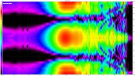
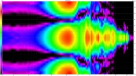
I investigated little more support construction behind the tweeter.
Lobbing begin at about same angle where supporting construction will be visible from measuring point and frequency of first minimum is at about frequency what reflects from the support in opposite phase. When angle is increased, minimum will move to higher frequency as distance from support to measurement point will be shorter. Most probably it is reflection from support construction as this construction was not present at prototype measuring..
Lobbing begin at about same angle where supporting construction will be visible from measuring point and frequency of first minimum is at about frequency what reflects from the support in opposite phase. When angle is increased, minimum will move to higher frequency as distance from support to measurement point will be shorter. Most probably it is reflection from support construction as this construction was not present at prototype measuring..
Basically what happen, is nearly same as on first image in post What are some good example of baffle design to improve diffraction
Only in my case two souses will be present from angle 30 deg and with angle increase sources will be more on same distance, on linked post image souses are on same distance on 0 angle and one behind other in 90 deg. angle.
Only in my case two souses will be present from angle 30 deg and with angle increase sources will be more on same distance, on linked post image souses are on same distance on 0 angle and one behind other in 90 deg. angle.
Would the situation improve if you shroud the rear wave a bit? You could try placing a piece of insulation behind the tweeter. Maybe a couple inches of thickness.
I will continue to find improvement. Little strange is that currently supporting construction is made from 20 mm panel and all edges are rounded with radius about 9,5 mm and support closest edge to tweeter is not 100% parallel with tweeter vertical axis, but still reflections are significant.
Last edited:
The top/bottoms of the driver housings above and below the amt are parallel though. Maybe if you added a ramp to those areas, extended out to the front edge of the mid's housings would also help with reflections. Cardboard cut to fit as a try? Should look more like a tapered waveguide then on all four sides.
Made some new measurements.
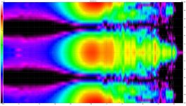
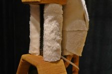
First wrapped support in "dead cat" (fake fur) like material in multiple layers and get this:

Then added same on the beams from front to speaker magnets, under that is also insulation foam layer.

Improvements are visible, only drop at about 4.5 kHz at 30-60 deg. remains.
But on image plot without fur on beams looks better.
This is how it looks

First wrapped support in "dead cat" (fake fur) like material in multiple layers and get this:
Then added same on the beams from front to speaker magnets, under that is also insulation foam layer.
Improvements are visible, only drop at about 4.5 kHz at 30-60 deg. remains.
But on image plot without fur on beams looks better.
This is how it looks
Attachments
This is how it looks
You've build a very nice cat scratch post there! 😀 Just kidding, that is a real improvement, that looks a lot better!
I made more calculations and tweeter first dipole (H-frame) peak must be at about 2150 Hz, first dipole minimum at 4500 Hz, fainting against them is nearly impossible if I want use Amtpro4 as H-frame OB.
Last edited:
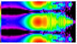
More measurements.
I was not sure about peaks and minimums and made measurements with ATMPRo4 closed back, closed with supplied felts. Mid is still as OB and filter is on 1 kHz.
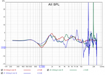
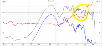
First polar plot

and on axis OB and closed back comparison in way closed/OB response.

From this measurements I understand first dipole peak is at 1 kHz somewhere, and first minimum at 2 kHz. Drop at 4 kHz is caused by speaker rear radiation and horn formed from beams, also horn is probably compensating dipole minimum on 2 kHz in OB configuration.
Can anyone tell how to change horn/beams shape to make directivity wider on 4,5kHz, or actually in range 4-10 kHz as seen from DI plot?

I was not sure about peaks and minimums and made measurements with ATMPRo4 closed back, closed with supplied felts. Mid is still as OB and filter is on 1 kHz.
First polar plot
and on axis OB and closed back comparison in way closed/OB response.
From this measurements I understand first dipole peak is at 1 kHz somewhere, and first minimum at 2 kHz. Drop at 4 kHz is caused by speaker rear radiation and horn formed from beams, also horn is probably compensating dipole minimum on 2 kHz in OB configuration.
Can anyone tell how to change horn/beams shape to make directivity wider on 4,5kHz, or actually in range 4-10 kHz as seen from DI plot?
Attachments
Last edited:
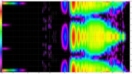
For comparison I dig out data based on what was generated images in first post, where ATMPRO4 is in original OB configuration without any beams or foam. I modified data to same gating window and polar plot range as on latest measurements, but it is without mid range speaker.
Attachments

Can anyone tell how to change horn/beams shape to make directivity wider on 4,5kHz, or actually in range 4-10 kHz as seen from DI plot?
That's easy. If the measurement before didn't show it and it does now, undo what you've done. You've put the felt on the waveguide, it seems it changes something for the better but it's not doing what you've thought it should do. Looks like the felt absorbtion isn't the same over the whole frequency range.
I don't understand why do you not simply remove them? You don't need the strips anyway. Or glue another pair of wood strips or in front of it, round off the back and side edges. Or use a board as baffle instead.
Look first and my previous post images.
Beams had also some advantage. If you look measurement of naked/original open back AMTPRO4, its polar plot is asymmetrical, minimum level is not on 90 degrees over all range. Beams made polar plot in OB configuration more symmetrical, but created dip on 4.5 kHz.
Closed back measurement was made to see pure forward radiation pattern, effect of beams and to understand in comparison with OB measurement where are peaks and nulls.
Partly question is also what is better: symmetrical font and rear radiation with dip on 4.5 kHz or asymmetrical radiation without 4.5 kHz dip.
Third option is to modify beams in way that symmetrical radiation is preserved and 4.5 kHz dip is removed.
Forth option is to live with this 4.5 kHz dip and enjoy music.
I can do changes, but first I am interested to find reason of the dip and to be sure changes will improve polar plot.
Last edited:
In this post can be find some tips: What's the Easiest DIY Unity Horn Project?
On my version beams with 5mm front plate form conical horn what had not the best polar plot. Response is not exactly same as conical horn had but something they had common.
On my version beams with 5mm front plate form conical horn what had not the best polar plot. Response is not exactly same as conical horn had but something they had common.
Look first and my previous post images.
Beams had also some advantage. If you look measurement of naked/original open back AMTPRO4, its polar plot is asymmetrical, minimum level is not on 90 degrees over all range. Beams made polar plot in OB configuration more symmetrical, but created dip on 4.5 kHz.
Closed back measurement was made to see pure forward radiation pattern, effect of beams and to understand in comparison with OB measurement where are peaks and nulls.
How did you measure? Did you turn the speaker or the AMT around to measure the back? What distance did you measure? Did you dampen the back when you measured it closed? And please don't be annoyed by that question even if others and I already asked that.
Partly question is also what is better: symmetrical font and rear radiation with dip on 4.5 kHz or asymmetrical radiation without 4.5 kHz dip.
I personally would prefer the more linear one and take the backward asymmetry. But: An asymmetry doesn't appear from itself because it feels like it, there has to be a reason. If you can rule out the room or other reflections, then it has to be the driver. Did you measure one vs. the other? The long diaphragm is critical. ESS had tons of problems and very high tolerances and the diaphragms changed over time in size, thickness and if one got damaged and you ordered a replacement, it was almost guaranteed you'd get a much different behaviour in distortion and frequency response. That's why you always have to buy them in pairs (either the complete driver or the diaphragms) and you do not buy the drivers if the ESS seal/sticker over the diaphragm insert slot is broken. On the ESS AMT-1, the membrane is on a molded plastic frame, which is often not plane in itself. ESS's answer to that? They mounted the frame on one side and on the other they put a 1cm piece play dough on it.
If you can rule reflections out and did not make errors on the measurements, then it has to be the driver itself. The Dayton AMT Pro-4 got a very bad review in a German forum, it was so bad after the first measurements he sent them back. If ESS didn't manage it in 45 Years to get it right, other manufacturers might have similar problems. For an asymmetrical dispersion the neodym magnet sticks, one of them might have lost power or were not correctly/fully magnetized in the first place. Or it got dropped on one edge with a hard impact but not on the whole driver with the same force. That's not unlikely and often happens, things very rarely drop flat and straigt, they tumble and turn. It could also be the mounting itself. Maybe the wood isn't completely flush/plane. Or the screws could be uneven tight. The driver itself could be bent, maybe not visibly, it's enough if the pole plate is bent or dented to get one side closer to the pole plate. I can't tell from the photos, from what I can see on them there's nothing unusual, that's just checking the possibilities.
Third option is to modify beams in way that symmetrical radiation is preserved and 4.5 kHz dip is removed.
Forth option is to live with this 4.5 kHz dip and enjoy music.
For the backwards radiation it isn't very important how symmetrical the dispersion is, the backside radiated sound give mostly 'roominess', depth, 'air' to the stage. That leads to a large depth but does not contain good precision of the location because it reaches the ear delayes so the brain does not calculate the position of it. The backwards sound got an influence on the tonality though, which will very likely impact the reproduction much more. But even that is not the end of the world, the room got surely not a symmetrical absroption and reflection, unless you specificly set it up for exactly this purpose.
I can do changes, but first I am interested to find reason of the dip and to be sure changes will improve polar plot.
I'd do this: Take the driver out of the speaker, mount it on a baffle (~50cm wide), measure it, front and back. The same with the 2nd AMT. Compare the measurements if the drivers themselves do not cause this problem. If you can't come to a clear conclusion from these measurements, then mount them again, relax and listen. If there's something you don't like, do more research or post pictures on where the speakers are standing and of the measurement setup, maybe someone can spot something we forgot so far. But if you can't pin it down from the sound and there are no distortion problems, let it be and take that version you like best.
Wise words from iCG. Every loudspeaker and driver has imperfections and some have individual flaws.
It is not easy for us amateurs to find out the cause(s) of imperfections in our speakers. One must do one change at the time and see what happens, then we get understanging of what is the cause. Sometimes we hit the wall, we can't make it any better in that direction, or making one criterion better some other(s) get worse.
With AINOgradient speakers I had many versions with different midranges and different tweeters and frame, some of them are not even in my thread! And it is not perfect even today. But it sounds good enough and to be honest, I can't even hear the problems that I know to exist. The worst problem is vertical directivity by the way, ten times worse off-axis dips and peaks!
Be patient, read other threads about dipole/open baffle, make protos, take measurements etc. Yes, frustration hits sometimes, but this is just a hobby!
- Home
- Loudspeakers
- Multi-Way
- AMT Pro-4 as OB tweeter