Because they don't add as if they areMy question remains, Why are the signal's not phase correlated?
") Sorry I don't have a better answer than what I said before, maybe Don can explain it in a different way.
Sorry I don't have a better answer than what I said before, maybe Don can explain it in a different way.Voltage is a vector, therefore above text is correct only, if there´s no phase difference.-voltage sum = 0.5V + 0.5V = 1.0V
To add a little to the confusion:
BW even order is Constant Power and not Constant Voltage
LR ( there is only even order ) is CV and not CP
Both crossovers have Allpass characteristics and main lobe is perpendicular to baffle.
BW odd order is CV and CP, no Allpass characteristics and main lobe shifts down, if both transducers have same polarity.
So far the theory with idealized transducers and then reality bites.
Real world transducers come with inherant Band Pass characteristics, so chances are really low, that one achieves an acoustic LR filter by applying electric LR crossover.
Flattening the drivers one octave above/below crossover may be sufficient for magnitude behaviour of 4th order crossovers but not for phase.
I thought the power dip was from this:
-voltage sum = 0.5V + 0.5V = 1.0V
-power ~ V^2
-power sum = (0.5V)^2 + (0.5V)^2 = 0.5 or -3dB dip
DonVK, this is clearly seen as spot-on math with regard to electrical signals.
But I have to keep asking all you guys, how does the -3dB dip apply to acoustic summation of two sources sharing same signal...each getting 1/2 voltage from original.
What happened to basic acoustic summation math?
The power sum equations posted assume correlated signal don't they?
Seems they have to.
If so, why throw out correlated signal post xover?
I'm asking, I don't get this...
Voltage is a vector, therefore above text is correct only, if there´s no phase difference.
To add a little to the confusion:
BW even order is Constant Power and not Constant Voltage
LR ( there is only even order ) is CV and not CP
Both crossovers have Allpass characteristics and main lobe is perpendicular to baffle.
BW odd order is CV and CP, no Allpass characteristics and main lobe shifts down, if both transducers have same polarity.
So far the theory with idealized transducers and then reality bites.
Real world transducers come with inherant Band Pass characteristics, so chances are really low, that one achieves an acoustic LR filter by applying electric LR crossover.
Flattening the drivers one octave above/below crossover may be sufficient for magnitude behaviour of 4th order crossovers but not for phase.
Hi Uwe, you've helped me see things straight more than once.
What's your take on an acoustic power dip in the xover region from LR xovers?
Away from that, my experience agrees that flattening drivers magnitude one octave above/below is usually not sufficient for flattening phase as well.
Takes some fine work to flatten mag further out and get the accompanying phase flattening..... and why i think available min-phase filter count in a non-FIR dsp becomes an issue..
It's also why i go with steep lin-phase, which always seems to work (provided the latency is ok).
It's incomplete.
There is a power dip as per the math above. I assume rms and in phase signals and LR4 XO. If it were heating or lighting you don't care about voltage phases and powers will add as per @fluids response. The relative phase matters when adding acoustic signals otherwise you could get a deep null as they cancel each other.
If I have 2 drivers that are exactly the same size, I get a 3dB acoustic gain that offsets the -3dB power dip. The net is zero.
If the drivers are different sizes there will be an acoustic dip. A 6.5in cone and 2in dome have about net -2dB dip at XO. A 2in dome and 1.125in dome will have a net -1dB at XO. Depending the driver size differences and on how picky you are, you might not notice.
...sorry for all the edits
Last edited:
Thx DonVK,
The same size drivers netting to zero makes sense.
I've never seen any acoustic summation math that has driver size as a variable, but then i guess there's always been an implied assumption in the calculators I've used, that the sources have identical properties .
What's the math/calculator that address's different size sources' summation at the same frequency? Like how you got that 6.5in to 2in, nets -2dB?
That's kinda blowing my mellon...(which ain't hard to do)
The same size drivers netting to zero makes sense.
I've never seen any acoustic summation math that has driver size as a variable, but then i guess there's always been an implied assumption in the calculators I've used, that the sources have identical properties .
What's the math/calculator that address's different size sources' summation at the same frequency? Like how you got that 6.5in to 2in, nets -2dB?
That's kinda blowing my mellon...(which ain't hard to do
)
Last edited by a moderator:
I would look at it as conversion efficiency from electrical watts to acoustic "watts". It's very low (<1%) for cones&domes. The drivers size impacts this conversion efficiency. If you decrease the electrical power, you will decrease the acoustic power for a given driver. There are formulas for driver efficiency in Kolbrek's Horn book. We also need to distinguish acoustic pressure (SPL) from acoustic power (watts) that is related by the radiation pattern. Most of the XO calculators use voltage and pressure.
I quoted measurements taken from the speaker (LR4 active, 3way) I'm currently working on. I don't try to calculate this drop. The LR4 is fixed and I adjust the sensitivity differences at the amps.
I quoted measurements taken from the speaker (LR4 active, 3way) I'm currently working on. I don't try to calculate this drop. The LR4 is fixed and I adjust the sensitivity differences at the amps.
Last edited:
My question remains, Why are the signal's not phase correlated?
My understanding (which very well may be a flawed understanding) is that the direct sound along an axis is correlated. So the LR2 and LR4 are both 6 dB down at the crossover frequency, and they sum to 0. This is true on axis, and off axis out to approximately 90 degrees horizontal.
The room response includes all the reflections. The signals from the two drivers become so jumbled by all the reflections that they are no longer correlated. If they are not correlated, the signals add based on power, not sound pressure. So the LR2 and LR4 will be -3 dB at the crossover when measuring the room response.
And for the record, I believe that the theoretical -3 dB crossover dip in the room response and the power response is relatively unimportant.
Electric xo and acoustic xo are different animals, and we are making it in acoustic domain with dsp. At least i can't see this kind of "power dip" in acoustic measurements when pre-xo responses are eq'd and delay/timing is matched. Timing error means phase match error... When timing is a tiny bit off, there is a dip in on-axis response and it's abit offset from xo-freq.
IRL (acoustic domain), driver directivity characteristics can easily give this kind of dip in acoustic power response, but it is a different scenario.
IRL (acoustic domain), driver directivity characteristics can easily give this kind of dip in acoustic power response, but it is a different scenario.
Last edited:
We also need to distinguish acoustic pressure (SPL) from acoustic power (watts) that is related by the radiation pattern.
Back to basics
Double amplifier power does not double the volume - Geoff the Grey GeekElectric xo and acoustic xo are different animals, and we are making it in acoustic domain with dsp. At least i can't see this kind of "power dip" in acoustic measurements when pre-xo responses are eq'd and delay/timing is matched.
IRL (acoustic domain), driver directivity characteristics can easily give this kind of dip in acoustic power response, but it is a different scenario.
Yes they are different but it is not about the on axis response but the acoustic power response. Because an LR filter is -6dB at the crossover point when the phases of the two drivers are incoherent they power sum to -3dB, the amount might change in reality due to differences between drivers, crossovers, directivity etc. But in a textbook case it will be very close to -3dB.
In a Butterworth crossover where the point is at -3dB incoherent summing will give a flat power response but a non flat axial response. The flat axial response with a slight power dip is the reason why the LR is so popular, it's a better trade.
How does a page on perceived volume level vs amplifier power help to understand the difference between coherent and incoherent summing?
Starting from the acoustic side which is where @fluid started.
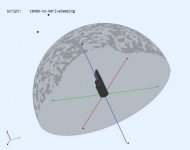
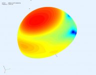
The pic below shows a speaker inside an observation hemisphere showing the SPL at all points on the hemisphere surface. Acoustic power is proportional to SPL^2 so if we integrated the SPL^2 over the surface we'll get total power. There is no need for phase or direction we just need SPL magnitude. This procedure would need to be done for every frequency of interest. To approximate we could sample surface points and sum the power (assuming its constant over some small surface area). This should also show power dips.
The pic below shows a speaker inside an observation hemisphere showing the SPL at all points on the hemisphere surface. Acoustic power is proportional to SPL^2 so if we integrated the SPL^2 over the surface we'll get total power. There is no need for phase or direction we just need SPL magnitude. This procedure would need to be done for every frequency of interest. To approximate we could sample surface points and sum the power (assuming its constant over some small surface area). This should also show power dips.
Attachments
Thanks for the link. Yes volume perception is a different animal. Distortion can make it sound loud. The test for 2x as loud was good and perplexed me abit. I can hear a 2db change easily but I never though about the "twice" as loud metric. I was actually surprised when I starting measuring SPL levels and realized how little power I actually need (aka Pano's survey).
C'mon now, there's no "jump" except when ypu eyeball the (usually theoretical) measurements.*...What is audible is the "jump" in the phase when the elements not are well enough aligned in the crossover section where both elements can be heard.
Im my case I can easily hear a 11 microseconds phase difference, in both crossover sections. At 400 Hz it is detectable as an "unclear" or "double" tone when playing a 400 Hz sinus wave.
At 2500 Hz I find it more revealing to listen to live recordings with emphasis on information in the crossover region.
Even though the phase warping not is directly audible, I experience a clear difference between LR4 and LR2 filters, which I connect to different "warping characteristics" (both have pros and cons and are good at different aspects).
In this sense "phase in general" also seems to have a kind of audibility.
Using trick test tones and doing a quick A-B switch, maybe differences can be detected (which rarely can be labelled good or bad). But then so many other factors can be switched inadvertently and inescapably, that lab test tones tell us little about audibility in the wild.
BTW, posts which report here to fore unreported subtle audible effects lead me to ask, "Have you ever done blind testing?" For example, you could ask your spouse to make the switch and see if you reliably tell A from B.
B.
* How about slow glide tones? Deserves a separate thread.
Last edited:
…But I have to keep asking all you guys, how does the -3dB dip apply to acoustic summation of two sources sharing same signal...each getting 1/2 voltage from original. What happened to basic acoustic summation math?...
If we stick with point-source monopoles, the math for the power summation is not that difficult, and should illustrate the concepts for the dip in the power response of LR4 crossovers. I personally think that the terms correlated & uncorrelated, are being used slightly outside of their original definition…but the concept is similar. The total acoustic power radiated by two point sources depends not only on the strength of the individual sources, but the distance between them and their relative phase. Imagine placing a large sphere around the sources and taking virtual microphone measurements all over the sphere. Then integrate the sound intensity (which is proportional to the square of the volume velocity) over the area of the sphere. This gives you the total acoustic radiated power of the two source system.…To approximate we could sample surface points and sum the power (assuming its constant over some small surface area). This should also show power dips.
See equation 3.3 in this article on sound radiation:
(PDF) Radiation of sound
Before jumping to the LR4 crossover, let’s look at the simpler example of two full-range point sources spaced 1/2 meter apart.
This will help illustrate how the terms correlated and uncorrelated relate to power response.
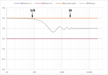
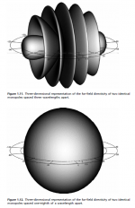
Attachment #1: With two +0dB sources, summation on-axis gives you the expected +6dB. However, looking at the power response, you can see that although the total radiated acoustic power increased by +6dB at low frequency it drops to +3dB at higher frequencies. Why is this?
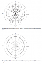
Attachment #2 & 3: If you look at the 2D and 3D representations of the polar response for 1/8 wavelength and 3 wavelength for the source separation distance things should start to “click”. At low frequencies, the phase difference between the sources is negligible for all locations on the sphere; you could say the source are correlated. At high frequencies, the phase difference between the sources varies dramatically from location to location on the sphere resulting in lobing; you could say the sources are uncorrelated. The higher in frequency you go, the more variation in phase between sources there is for a given movement on the sphere. In other words, the sources are becoming more uncorrelated and the total radiated acoustic power asymptotically approaches +3dB. This power response curve is what you would measure with an RTA if you placed these 2 sources in a perfectly reflective room.
With this example as a foundation, I’ll post similar plots and explanations for the LR4 crossover after lunch.
For those with AES memberships, you might find the following paper of interest:
"Power Response of Loudspeakers with Noncoincident Drivers -- The Influence of Crossover Design,"
J. Vanderkooy & S.P. Lipshitz, J. Audio Eng. Soc., Vol. 34, No. 4, pp. 236-244 (Apr. 1986)
AES E-Library >> Power Response of Loudspeakers with Noncoincident Drivers-The Influence of Crossover Design
Attachments
Last edited:
Thank you bolserst, DonVK, fluid, everyone....
It all came clear in a mid-night wakening...like so many things do when we wake up in middle of night continuing to think about our beloved/cursed audio lol...
and all your posts make sense now.
It kinda hit me, if any cancellations arise anywhere in the polar response, which we know they do, they have to reduce the integrated power response summation across the frequency range from the perfect +6dB of two equal sources.
I do think the terms correlated vs uncorrelated were misleading (for me anyway) ... I'd describe it more in terms of acoustic radiation from two sources in phase, vs two out of phase.
and i think the wattage power dip stuff is nearly total misdirection, because it appears to ignore the real directionality vs freq map behind acoustic power response.
Thx again all and I'm sure there's more for me to learn here...
It all came clear in a mid-night wakening...like so many things do when we wake up in middle of night continuing to think about our beloved/cursed audio lol...
and all your posts make sense now.
It kinda hit me, if any cancellations arise anywhere in the polar response, which we know they do, they have to reduce the integrated power response summation across the frequency range from the perfect +6dB of two equal sources.
I do think the terms correlated vs uncorrelated were misleading (for me anyway) ... I'd describe it more in terms of acoustic radiation from two sources in phase, vs two out of phase.
and i think the wattage power dip stuff is nearly total misdirection, because it appears to ignore the real directionality vs freq map behind acoustic power response.
Thx again all
and I'm sure there's more for me to learn here...When the two sources are not full range but rather tweeter/woofer with associated HP/LP crossovers, the lobing behavior leading to a -3dB drop in power response only happens in the crossover range where both sources have similar output magnitudes. As shown in the previous post, the lobing also only happens if there is significant difference in phase between the two sources as you move around the sphere. With LR4 crossovers, the tweeter and woofer are in phase throughout the crossover range. So, the only possibility of phase differences occurs from the separation distance between them.
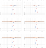
If the separation distance is kept < λ/10 at the crossover frequency, there will be minimal dip in the power response. The attachment summarizes the power response for a range of separations distances “d” for a 1kHz LR4 crossover between two ideal point sources. As soon as you start dealing with real size woofers and tweeters, their inherent directivity will generally cause more droop in the power response than what you get due to the level of phase correlation between the spaced drivers. All that to say, in my experience it is more of a theoretical issue than a real world problem.
If the separation distance is kept < λ/10 at the crossover frequency, there will be minimal dip in the power response. The attachment summarizes the power response for a range of separations distances “d” for a 1kHz LR4 crossover between two ideal point sources. As soon as you start dealing with real size woofers and tweeters, their inherent directivity will generally cause more droop in the power response than what you get due to the level of phase correlation between the spaced drivers. All that to say, in my experience it is more of a theoretical issue than a real world problem.
Attachments
I agree. Generally when you see correlated or uncorrelated signals being discussed(ie like pink noise test signals) it has nothing to do with spacial variance of the phase....I do think the terms correlated vs uncorrelated were misleading (for me anyway) ...
Your explanation and diagrams are definitely a better way to understand it. I hope you find the time to post the LR4 information. Edit: Looks like you did just as I posted.If we stick with point-source monopoles, the math for the power summation is not that difficult, and should illustrate the concepts for the dip in the power response of LR4 crossovers.
With this example as a foundation, I’ll post similar plots and explanations for the LR4 crossover after lunch.
I would like to read that AES paper as I have read the paraphrased conclusions of it in many places but never the article itself.
I'm glad your melon did not explode trying to wrestle with itIt all came clear in a mid-night wakening...
I do think the terms correlated vs uncorrelated were misleading (for me anyway) ... I'd describe it more in terms of acoustic radiation from two sources in phase, vs two out of phase.
It's hard to quote someone (Douglas Self) without using the terms they use, sengpielaudio uses similar terms in their calculators they even put in phase in brackets next to correlated - Status
- This old topic is closed. If you want to reopen this topic, contact a moderator using the "Report Post" button.
- Home
- Loudspeakers
- Multi-Way
- Active LR4 crossover phase matching using a DSP