This frequency response (FR) which "sums up flat" in LR should not get so much attention because you can still only measure sound pressure level (SPL) in a room, wich tells you LR is not flat.
No it happens either way, in phase or inverted. You can see the two graphs above. What changes is the all pass response and group delay peak.It happens because they are not in phase...
Can you explain what you mean here?The slopes (in this case) are the same, the amount of difference is important, but they don't match.
SPL is flat on axis, it's only the power where there is a dip in most cases around the crossover point. An in room measurement is not the same thing as heard by your ears processed through your brain.This frequency response (FR) which "sums up flat" in LR should not get so much attention because you can still only measure sound pressure level (SPL) in a room, wich tells you LR is not flat.
Not polarity. They are 90 degrees out of phase at all frequencies regardless of polarity.No it happens either way, in phase or inverted.
With polarities the same, a Bu3 has 270 degrees of phase difference between output.
With inverted polarities, it has 90 degrees difference between outputs.
This may be mistakenly thought to be 90 degrees either way,
if someone equates 0 degrees phase and 360 degrees phase as being equal.
They are not equal. As shown by fluid's graph of group delay in #199.
Bu3 is a good xover. It's a compromise xover where worst case (polarity normal) is still OK.
Biggest issues imo are the lack of slope, being only 3rd order; and lobing.
It's my go-to xover for live sound when asked to help setup other folk's rigs, and there is no time to measure subs to mains.
Like said, great compromise xover.
...
One benefit of the LR crossover is that the main lobe points straight ahead, if you tilt the baffle you will also tilt the lobe.
...
It is about here I get lost when it comes to the effects of baffle tilting.
My understanding of lobes is that the effect comes from having the same signal sent from two sources with a (in this case) vertical distance between them. The lobe direction comes from the timing between the elements, and will be straight ahead if the two sources are in the same vertical plane, or in this case if one of them is delayed so that the signal reaches the listening position simultaneously.
This is another way to say that the phase is aligned (at the listening position) in the crossover section where sound from both elements is heard.
It is the timing, i.e. phase, that determine the lobe direction, not the baffle angle.
With this background my understanding is that it is the phase alignment that makes the lobe point straight ahead, and that the lobe angle "straightness" is improved with tilting the baffle, not reduced.
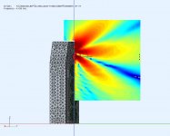
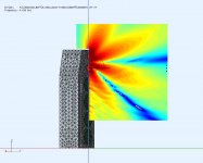
This speaker uses an active LR4 XO. The first pic is for the M+T drivers in phase and the center lobe points straight out between the drivers @XO. The second pic has the tweeter reversed (ie. 180deg phase) and you can see the axial null between the drivers due to interference. It also has more lobes that are no longer pointed at the listener.
At some frequency, away from the XO point, each driver will be dominate and will radiate straight out axially. So it makes some sense to have the same behaviour at the XO point when both drivers are active.
I would think that adjusting the drive level of multiple "in phase" drivers would allow you to steer the beam. As long as the total power was constant so that the FR remained flattish.
That lobe pattern follows the driver's axis which are fixed to the baffle (as per @fluid).
Attachments
Plus or minus 90 degrees? Isn't the difference in group delay due to the 1.1mS delay?
my 2c
Yeah, it would seem plus or minus 90 degrees is an accurate description, but it's not. It really is 90 vs 270.
It's a highway to disaster to think every 360 is equal phasewise.
The difference in group delay curves we've seen is about polarity, not any timing pulled out from group delay.
On graph below:
Red curve is #1 trace alone, which is both sides of a Bu3 @300Hz summed with normal polarities.
Blue curve is traces #2 and #3, which are the same, where both sides are summed, inverting each side one at a time.
Those two are the same as fluid showed, just shown again for extra perspective against what follows.
Now for the group delays of the two sides separately.
#4 is low side only with normal polarity; then #5 the same but inverted.
#6 is high side only with normal polarity, then #7 the same but inverted.
If you couldn't pick them out it's because they are all the Green curve... #4-7 are all the same.
No differences.
Which is why polarity matters to summed output.
When both are normal, the same group delay curves appear to become somewhat additive, and give trace #1.
When one side is inverted they appear to become become somewhat subtractive, and give traces #2 or 3.

I'm guessing the 1.1ms you quoted, is like what REW will show as delay relative to loopback difference between low and hide sides. ????
Continuing with that guess...
For the high side, either polarity, delay will be 0ms.
For the low side, either polarity, delay will be very close to the 1.1ms quoted.
But that 1.1ms is not group delay.
It is a representation of group delay at a particular frequency......
....since group delay is a frequency dependent curve, not a constant time.
(Which is why it makes a poor substitute for offsetting acoustic center timing differences, that need a fixed time constant to properly offset.)
I believe the represented frequency @1.1ms delay is at the average of the frequencies where phase wraps occur for the individual low pass and high pass sides with normal polarities.
But i do not know this for certain. Anybody have the definitive scoop here?
Last edited:
ThisI'm guessing the 1.1ms you quoted, is like what REW will show as delay relative to loopback difference between low and hide sides. ????
This is synthetic 300 Hz BW3, phase slopes aligned in REW with a 1.1ms delay,
I don't know anything about REW, I've never used it. I thought the delay had been added
This
I don't know anything about REW, I've never used it. I thought the delay had been added
Gotcha. Thx.
No delay was involved in my graphs.
I don't use simulations for exploring xovers.
The traces posted are measurements of a processors output, simply summed (or the two individual sides as stated)...with no delays.
It may be when building/exploring synthetic xovers, perhaps via imports from rephase, that alignment is needed in REW?
Dunno...and don't want to speak for fluid.
Last edited:
Earlier a poster said he didn't think Unity/Syngery was relevant. Why not? Those speakers require that adjoining drivers are within 1/4 wavelength at crossover frequency. This is one factor required for virtual point source behavior. Obviously not all speakers can do this: good luck doing it with most two-ways! Of course speakers that are > 1/4 wave length apart can still sound good. Yet, as I understand things, the problems of lobing, nulls and so on, are the direct consequence of two drivers not being within 1/4 wavelength. You can correct for on-axis response sure. This may or may not be relevant, but you cannot escape the problem of nulls or off-axis response divergences. It likely is relevant if you are listening in a real-world space that has significant reflection.
Last edited:
There’s an informative article about crossovers and lobing due to driver separation here: Power. When reading, keep in mind that they are discussing two sources, i.e. both drivers are completely omnidirectional at the crossover point and no acoustic offset differences.
Thanks for that. Very interesting.
Whats' your take on using two omnidirectional point sources to come to such definitive conclusions?
Must admit, on first read it seems like a stretch....but it's just another one of the never ending cases of me not knowing enough, to know what to think 🙂
Earlier a poster said he didn't think Unity/Syngery was relevant. Why not? Those speakers require that adjoining drivers are within 1/4 wavelength at crossover frequency. This is one factor required for virtual point source behavior. Obviously not all speakers can do this: good luck doing it with most two-ways! Of course speakers that are > 1/4 wave length apart can still sound good. Yet, as I understand things, the problems of lobing, nulls and so on, are the direct consequence of two drivers not being within 1/4 wavelength. You can correct for on-axis response sure. This may or may not be relevant, but you cannot escape the problem of nulls or off-axis response divergences. It likely is relevant if you are listening in a real-world space that has significant reflection.
Agree Soldermizer, why not? especially now that discussion has turned toward lobing issues.
I've become convinced that achieving 1/4 wl spacing throughout summation regions is the name of the game for making a truly great speaker....don't care what kind it is.
I think it helps in multiple ways: lobing reduction and hence power response, an electrostat like on-axis focus, keeping a line array together, on and on, etc...
I also think the more 1/4 wl spacing is accomplished, the more audible all the fuss becomes with spot on tuning, including pretty flat phase .
And if one wants to control directivity to further manage the off axis response a waveguide is needed. Multiple entry horn is pretty much the only thing that can achieve the goal of 1/4wl spacing and controlled directivity. A true point source 🙂
No same delay for both mark answered the why in his posts.Plus or minus 90 degrees? Isn't the difference in group delay due to the 1.1mS delay?
It had, you are right there.I don't know anything about REW, I've never used it. I thought the delay had been added
Yes the delay needs to be added to ensure the phase is aligned and you get the sum you want. In a real speaker the offsets will be different and you might get lucky or design it so there is no extra delay added.It may be when building/exploring synthetic xovers, perhaps via imports from rephase, that alignment is needed in REW?
Dunno...and don't want to speak for fluid.
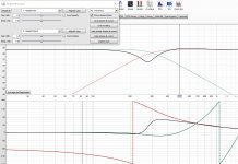
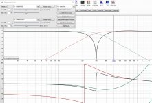
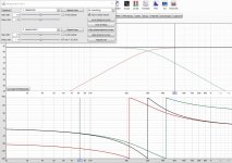
Here are some graphs from the alignment tool in REW to show what happens when the relative phases are changed. This is using the 'both drivers in phase' version. This is why I say the slopes need to be aligned, the phase matched option in REW gives the maximum peak, so I suppose the terminology can be confusing but the graphs show what is happening. The only thing changing is the delay / relative phase between sides.
Attachments

REW is wrong on this.
To display phase one needs to set a reference point in time.
What RWE is doing :
It takes the IR of the Low Pass and finds the peak, uses this as reference to plot the phase of the LP.
Then it uses the peak of the HP´s IR ( which is different ) to plot that phase.
To compare two phase traces, one always needs the same reference time ( delay ).
Why is this easy to spot:
In simulated HP/LP there is no time of flight involved, therefore the phase trace should always be going down ( except for REW 🙂 )
The phase plot of REW for the LP generates negative Group delay, which is second best to time travel 🙂
Last edited:
That can be the case and is shown graphically here, but if you have a straight polar lobe then tilt the baffle the lobe will tilt with it tooIt is the timing, i.e. phase, that determine the lobe direction, not the baffle angle.
With this background my understanding is that it is the phase alignment that makes the lobe point straight ahead, and that the lobe angle "straightness" is improved with tilting the baffle, not reduced.
All odd order crossovers have a tilt baked into them scroll down to the bottom of this page for some graphical examples
Power
They can be tilted back up but it is just another thing to consider as to which is the best compromise for the application
Attachments
- Home
- Loudspeakers
- Multi-Way
- Active LR4 crossover phase matching using a DSP