Hello all!
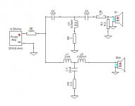
Before Christmas I decided I would start work on my first speaker design. After some looking around I decided I'll try my hand at building something with the two drivers mentioned in the title. I admit I could have probably done a better job at picking the drivers, alas this is what I arrived at. I have not gotten tremendously far, as I am currently finishing my degree in electrical engineering.
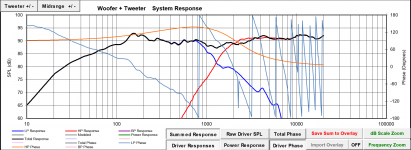
I am planning on placing the crossover somewhere between 1000 and 2000 Hz. I have read a couple of contradicting perspectives about where the LPF on the tweeter should be, some say go high, some say you can take it low.
I have reached a reasonable crossover network. I would however like to ask for some input on how I could improve this, as I am not entirely happy with the phase characteristics.
PS. I am using the late Jeff Bagby's Passive Crossover Designer Excel spreadsheet.
PPS. I could not find .frd files for the woofer I am using so I used the .frd files I found for its 8ohm version, and keeping the differences in response in mind. I was going to measure the impedance and frequency characteristics of both drivers with the measuring devices at uni, but this whole pandemic got in the way.
Before Christmas I decided I would start work on my first speaker design. After some looking around I decided I'll try my hand at building something with the two drivers mentioned in the title. I admit I could have probably done a better job at picking the drivers, alas this is what I arrived at. I have not gotten tremendously far, as I am currently finishing my degree in electrical engineering.
I am planning on placing the crossover somewhere between 1000 and 2000 Hz. I have read a couple of contradicting perspectives about where the LPF on the tweeter should be, some say go high, some say you can take it low.
I have reached a reasonable crossover network. I would however like to ask for some input on how I could improve this, as I am not entirely happy with the phase characteristics.
PS. I am using the late Jeff Bagby's Passive Crossover Designer Excel spreadsheet.
PPS. I could not find .frd files for the woofer I am using so I used the .frd files I found for its 8ohm version, and keeping the differences in response in mind. I was going to measure the impedance and frequency characteristics of both drivers with the measuring devices at uni, but this whole pandemic got in the way.
Attachments
Thanks, im on it!You would probably get a lot more help if you could transplant your design into XSim and upload the DXO file it creates. This would give us access to both the speaker parameters and the crossover schematic...
Okay ... thanks for the DXO
I had a bit of a play with it and you may find this helpful...
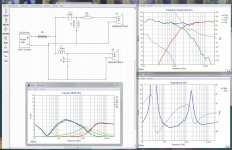
In the first thumbnail I jacked up the amplifier power to 100 watts and added R5 which is just a shorted resistor so I could see the total current.
At 100 watts for 8 ohms you should expect to see about 4 amps total. If you note your shunt components were drawing a fair bit of current causing some inefficiency as not all the current was getting to the drivers.
Tinkering with part values trying to reduce these inefficiencies lead me to a bog standard 2nd order design that you can see in thumbnail #2. Note that the shunt currents are reduced and now occur in the higher impedance region of the crossover point.
I was also able to reduce the rising high frequencies of the original design somewhat by going to a simple series resistor on the tweeter.
This should be a more efficient speaker.
Note that everything is now within plus or minus 3db except for the rise in output of your woofer at lower frequencies, which is kind of a natural baffle step compensation.
Hope that helps....
I had a bit of a play with it and you may find this helpful...
In the first thumbnail I jacked up the amplifier power to 100 watts and added R5 which is just a shorted resistor so I could see the total current.
At 100 watts for 8 ohms you should expect to see about 4 amps total. If you note your shunt components were drawing a fair bit of current causing some inefficiency as not all the current was getting to the drivers.
Tinkering with part values trying to reduce these inefficiencies lead me to a bog standard 2nd order design that you can see in thumbnail #2. Note that the shunt currents are reduced and now occur in the higher impedance region of the crossover point.
I was also able to reduce the rising high frequencies of the original design somewhat by going to a simple series resistor on the tweeter.
This should be a more efficient speaker.
Note that everything is now within plus or minus 3db except for the rise in output of your woofer at lower frequencies, which is kind of a natural baffle step compensation.
Hope that helps....
Attachments
Last edited:
Thank you, I really appreciate it! I will take a better look at it in the morning, but what you say helps heaps. I hadn't really considered the efficiency of the crossover network, I got too carried away with trying to get the FR and PhR right ;D.
PS. I'll probably have some questions later on if you don't mind.
PS. I'll probably have some questions later on if you don't mind.
Last edited:
I hadn't really considered the efficiency of the crossover network,
Many designers don't. As a result we tend to have very inefficient speakers with only marginally better frequency response and a huge demand for power. In some cases an inefficient crossover can kill an amplifier.
PS. I'll probably have some questions later on if you don't mind.
I will be happy to try to help ... I'm hoping the others will too.
Last edited:
Have you considered putting the SB29RDC-C004 on a waveguide? it would allow you to cross lower.
SBAcoustics SB29RDC How low would you go?
SBAcoustics SB29RDC How low would you go?
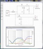
Tricky. I don't know about your original files. Using minimum phase makes a difference, and considering you didn't measure I'd be suspicious. I also figured in a little delay for the tweeter.I am not entirely happy with the phase characteristics.
This appears to provide adequate summation.
Attachments
Before you buy any crossover parts I recommend you get some measurements of the drivers in your box and then design the crossover. Almost any cheap capsule microphone that plugs into your PC will work well enough to design a crossover. Free software like REW or Arta can save the files needed to load into Xsim.
Hello all!
PPS. I could not find .frd files for the woofer I am using so I used the .frd files I found for its 8ohm version, and keeping the differences in response in mind. I was going to measure the impedance and frequency characteristics of both drivers with the measuring devices at uni, but this whole pandemic got in the way.
What I gave you was the basic design, once you have the correct files you will just need to tinker with the part values to get it back to where I showed it.
Tricky. I don't know about your original files. Using minimum phase makes a difference, and considering you didn't measure I'd be suspicious. I also figured in a little delay for the tweeter.
This appears to provide adequate summation.
And where's the DXO file? As it is right now you have the tweeter down nearly 20db at the high end... you've inverted both drivers... And you've pushed the crossover up to nearly 2500hz ...
I guess the only question is ... What were you thinking?
Let's look at what you're dealing with.
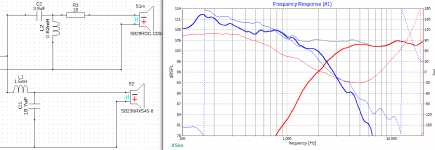
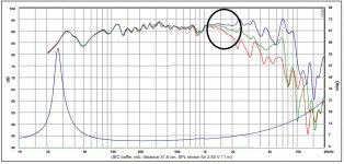
Pic 1 shows Zaph's measured HD for the SB 29RDC. You definitely want to cross it over before the 3rd harmonic starts to climb too high. So minimum about 1500Hz or so and I would go steep, closer to 4th order acoustic.
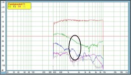
Pic 2 shows where the off-axis response starts to diverge from the on-axis response for the SB 23RNXS45-4. The rule of thumb is to cross before the response 45 degrees off-axis exceeds -3dB from the on-axis response. Measured are the 30 and 60 degree responses so somewhere again around 1500Hz is where you are going to want to cross this puppy.
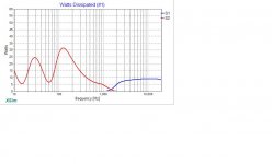
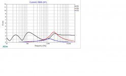
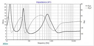
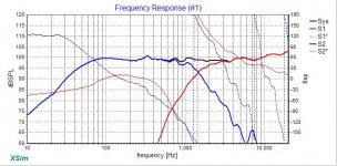
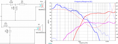
Pics 3, 4 and 5 show the SB 23RXNS45-4 and the SB 29RDC in XSim. The files include the vented response of the woofer in 34L tuned to 30Hz and the baffle diffraction on an 11" x 26" front baffle with the woofer centered about 16" up from the bottom and the tweeter 4.75" from the side and about 23" from the bottom. I included a 1/2" radius in the sims. You may choose to do something different. This was just to get something into the ballpark. From the mechanical drawings of the drivers, I measured for acoustic centers and arrived at a guestimate of a 1.6" delay for the woofer.
I went 3rd order electrical on both drivers to get the steeper acoustic slopes that I think are necessary in this application. Minimum phase was extracted from all the files using XSim (except tweeter Z because I had it already) and the phase responses align fairly well in the xo region. That could maybe be improved with a little bit more time and tweeking. Impedance minimum sits at about 4ohm just above 100Hz. Sensitivity ends up at about 86dB with 1W at 1m with the full baffle step loss taken into account. You only need 20W to get to about 100dB at 1m which will be screaming in a medium size room and is the level used in the attached graphs.
Pic 6 shows the current draw with 20W for the system as a whole and then for the parallel legs on the tweeter and woofer, all perfectly acceptable with a minimum 100W amp. And Pic 7 shows the actual watts dissipated for each driver. Importantly, the woofer is actually drawing more than 20W at each of its lower impedance points so a little extra headroom on your amp would appear to be a good idea. Again, minimum 100W should do it. More never hurts. That's unless you want to go louder than what I've shown.
Also attached is the XSim file to play around with. Other tweeks, fine tuning or alternate typologies are certainly possible but the new frd and zma files are there for you.
Hope that helps.
Pic 1 shows Zaph's measured HD for the SB 29RDC. You definitely want to cross it over before the 3rd harmonic starts to climb too high. So minimum about 1500Hz or so and I would go steep, closer to 4th order acoustic.
Pic 2 shows where the off-axis response starts to diverge from the on-axis response for the SB 23RNXS45-4. The rule of thumb is to cross before the response 45 degrees off-axis exceeds -3dB from the on-axis response. Measured are the 30 and 60 degree responses so somewhere again around 1500Hz is where you are going to want to cross this puppy.
Pics 3, 4 and 5 show the SB 23RXNS45-4 and the SB 29RDC in XSim. The files include the vented response of the woofer in 34L tuned to 30Hz and the baffle diffraction on an 11" x 26" front baffle with the woofer centered about 16" up from the bottom and the tweeter 4.75" from the side and about 23" from the bottom. I included a 1/2" radius in the sims. You may choose to do something different. This was just to get something into the ballpark. From the mechanical drawings of the drivers, I measured for acoustic centers and arrived at a guestimate of a 1.6" delay for the woofer.
I went 3rd order electrical on both drivers to get the steeper acoustic slopes that I think are necessary in this application. Minimum phase was extracted from all the files using XSim (except tweeter Z because I had it already) and the phase responses align fairly well in the xo region. That could maybe be improved with a little bit more time and tweeking. Impedance minimum sits at about 4ohm just above 100Hz. Sensitivity ends up at about 86dB with 1W at 1m with the full baffle step loss taken into account. You only need 20W to get to about 100dB at 1m which will be screaming in a medium size room and is the level used in the attached graphs.
Pic 6 shows the current draw with 20W for the system as a whole and then for the parallel legs on the tweeter and woofer, all perfectly acceptable with a minimum 100W amp. And Pic 7 shows the actual watts dissipated for each driver. Importantly, the woofer is actually drawing more than 20W at each of its lower impedance points so a little extra headroom on your amp would appear to be a good idea. Again, minimum 100W should do it. More never hurts. That's unless you want to go louder than what I've shown.
Also attached is the XSim file to play around with. Other tweeks, fine tuning or alternate typologies are certainly possible but the new frd and zma files are there for you.
Hope that helps.
Attachments
-
SB 23RNXS45-4 + SB 29RDC.dxo54.8 KB · Views: 25
-
 XSim W SB23 + 29.jpg62 KB · Views: 82
 -
 XSim A SB23 + 29.jpg62.6 KB · Views: 84
 -
 XSim Z SB23 + 29.jpg63 KB · Views: 369
 -
 XSim FR SB23 + 29.jpg72.8 KB · Views: 390
 -
 XSim xo SB23 + 29.jpg16.9 KB · Views: 397
 -
 SB 23RNXS45-4 FR.jpg164.1 KB · Views: 380
 -
 SB 29RDC HD.jpg217.8 KB · Views: 424
Thank you Douglas. In my effort to get into discussing phase, the crossover frequency strayed.
As I mentioned earlier this is not a ready for production crossover, rather an exercise.
As I mentioned earlier this is not a ready for production crossover, rather an exercise.
Why don't you do the same?you have the tweeter down nearly 20db at the high end... you've inverted both drivers...
Attachments
@jreave ..
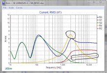
Jack your amplifier power up to 100 watts ... you will see that you are pulling some pretty significant current through the L3 R4 chain and through R2. Your tweeter is actually only getting about half of the current from the amplifier, so the rest is just wasted.
In fact R2 would need to be a 25 watt resistor if you don't want to burn it out.
And, in reality, your response is not significantly better than either the original or mine.
Attachments
Last edited:
Why don't you do the same?
Why would I?
And I don't think our friend is looking for a theoretical discussion.
Last edited:
@jreave ..
Jack your amplifier power up to 100 watts ... you will see that you are pulling some pretty significant current through the L3 R4 chain
One other quick point... if you look at the current in the L3 R4 chain at one point it exceeds the total current from the amplifier, this could indicate resonance and ringing in the crossover circuit.
For christiank24,
If you happen to be using my posted XSim files, I realized I made a small mistake last night. I input the acoustic center difference between the drivers the way I would do it in PCD whereas in XSim, one needs to do the calculations that PCD does automatically to come up with the difference in path length from the drivers to your measuring point. Instead of 1.6", it should be closer to 2". Makes phase alignment even a little more difficult. Also makes putting the tweeter into a waveguide an even better idea although I might try without it to start off with and see how it goes. In that instance though, I still think steeper xo slopes is the way to go.
For Douglas,
I quite appreciate the attention to current and wattage that you have brought to the discussion lately. I think it is theoretically helpful, but in practical terms, not so much. We may have to agree to disagree on this one, but I don't see any practical point in using an arbitrary power value of 100W to decide if the current flow is excessive for the amp. If I want to run 100W into the speaker (which I don't), then I'm going to want headroom to do so. If I go with 6dB of headroom, I would therefore be using an amp capable of 400W into 4ohm. Available current would therefore be 10amps and so the amplifier would be safe in the example you have used with maximum current draws of 5amps and in my example, with max current draws of 7amps.
In this case with the SB woofer, max RMS power is 60W and xmax will be exceeded in the LF's with greater than 40W in a vented box and the result in either case would be more SPL than I would ever want to listen to. How the OP wants to use these is as yet undetermined, but it makes more sense to me to look at current and power consumption only in terms of expected max SPL's relative to the maximums that an amp is capable of producing. Thus in my example, I used a max of 20W for about 104dB at 1m and suggested a minimum of a 100W amp. All is safe within these parameters unless there is something here I don't understand.
In this context, I accept that speakers are inherently inefficient. I am all for diminishing this to as little as possible but I am also willing to live with the inefficiency if it gets my drivers to the target responses I want for them and therefore a better sounding speaker.
- Status
- This old topic is closed. If you want to reopen this topic, contact a moderator using the "Report Post" button.
- Home
- Loudspeakers
- Multi-Way
- Designing an 8" 2-way using the SB23NRXS45-4 and SB29RDC-C004