No EQ, just raw drivers. I found them used with horns from Denmark and a pair of 15pr400 used from Sweden. Good that the graphs look easy to work with - I'm trying to "design" my first pair of speakers and have never done a crossover=)
The graphs look rather similar to me, so I will go with the xt1464 since discussion here gives the impression that it is slightly preferred to lth142, does this seem resonable?
I think you should mount them in a test baffle with approx. the dimensions you plan to use before deciding. It will give a smoother low end.
I plan to build exactly the same system with 15PR100 and HF1440/LTH142! Maybe we should share our experiences

I see it too. ATH4 optimised horn. 1M.
Interestingly enough there is a peak in the impedance plot at this frequency in the Faital Pro data, but no response irregularity.
One thing to note from my side. The wg does not provide any load or damping to the driver? A good horn also damps significantly all peaks visible in the free air impedance shot of the driver. A good example is the 18s ND4015N attached to Selenium HL4750SLF horn which provides excellent loading / damping. Red is free air.

I think you should mount them in a test baffle with approx. the dimensions you plan to use before deciding. It will give a smoother low end.
I plan to build exactly the same system with 15PR100 and HF1440/LTH142! Maybe we should share our experiences
that's a funny coincidence. We could start a separate thread for our italohifi-projects! Mine will take a lot of time though.
The dip seem to occur exactly where the driver's impedance side peak is. If we assume simply that P = U**2 / R then the voltage source amp might provide much less output power P into the bigger load R resistance.
What I would try now is a setup with amp out following first a 10 ohms parallel resistor and after this an 100 ohms resistor in series with the driver.
The difference would then be about 108 (normal) to 140 (peak) and without this setup 8 to 40.
thanks for the clear explanation - will try this at first opportunity!
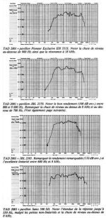
I have found some old material by JMLC and will attach this here. Unfortunately it is in frech but maybe we have some native speaker to translate this correctly.
Here is an extract:

and the paper:
View attachment creux_1900Hz_TAD_TD2001.pdf
I could not find a picture of the measurement setup. maybe it is written in the text.
Here is an extract:
and the paper:
View attachment creux_1900Hz_TAD_TD2001.pdf
I could not find a picture of the measurement setup. maybe it is written in the text.
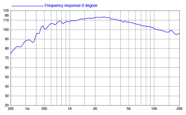
I'm trying to measure the exit angle of the HF1440. The angle is definitely negative: the exit throat is narrowing towards the exit. Unfortunately, my caliper's extension wasn't long enough to measure the exit cone inside it. Assuming a constant wall thickness of the exit cone, I measured it from the outside. The exit angle of the HF1440 is -0.86° measured over last 10mm.
Tried this driver on a Joseph Crowe ES-600 horn. The frequency response is smoother than using RC HF950 horn, but the ES-600 horn seems to be losing vertical directivity at about 1500Hz and in-room measurements tell very little. I had to use strong smoothing and short window to get something meaningful.
Attachments
-lots of pillows piled on the floor around (and under in this case) the device under test and in-between and around the mic. If it’s just the horn/CD you can also lower it nearer to the pillow stack to delay the ceiling reflection. You can also move closer to the source but in this case I would not recommend closer than 18”s.
Translated English version added.I have found some old material by JMLC and will attach this here. Unfortunately it is in frech but maybe we have some native speaker to translate this correctly.
Here is an extract:
View attachment 979411
and the paper:
View attachment 979412
I could not find a picture of the measurement setup. maybe it is written in the text.
What equipment JMLC used to measure or the setup is not so important. His "paper" was done to show the effect of resistive padding/ "high" output impedance amps on a compression driver.
It has been documented numerous times, that the TD-2001 has this issue.
Look at the added pic of some old TD-2001 measurements, they all show it to some degree..
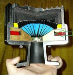
It is a cavity resonance, due to the cavity in the gap, below the drivers voice coil due to too large clearances.
Look at the attached picture below of a split up 4002, and the added arrow, you can see the "black rubber ring" added below the gap to avoid a cavity resonance during the design phase.
Don't take my word for it. If your a AES member or find it elsewhere, this document below gives some insight into the problem in general, and for the TD-2001. Written by Kinoshita and Locanthi in 1978 the year they released the TD 4001 and 2001. Noone would know better in the case of the TD-2001.
The Influence of Parasitic Resonances on Compression Driver Loudspeaker Performance
https://www.aes.org/e-lib/online/browse.cfm?elib=2932
The Faital HF10AK has a similar issue as has been seen on several measurements, like:
Look at the CSD, sonogram, and distortion measurement and the issue becomes visible, you can also see the impedance/phase without a horn having a irregularity there.
https://www.dibirama.altervista.org...faital-hf10ak-driver-1-73-8-ohm-120-wmax.html
I would not be suprised if the resistive padding or a high source impedance amp will smooth out some of what is shown in that driver too. There are several users here on the forum that will know that better then me.
As in the case of the HF1440, @chebum should get some extra ideas from JMLCs document using resistive padding and testing, also the dibirama measurements is a good pointer on how to discover such a problem.
Attachments
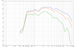
HF1440 looks smoother at high end than HF146, the drop can easily handled by EQReally nice driver, indeed!
But you have to keep in mind that the driver efficiency above 10KHz is only 100dB; while the HF146 is much better above 10KHz:
HF1440:
HF146:
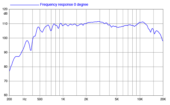
Please note that the scales are way off:HF1440 looks smoother at high end than HF146, the drop can easily handled by EQ
This is a much fairer comparison.
Thanks for this overlay, read through the topic and it made me wiser but equally more confused.
I've seen a few 'favorites' in this topic which all cost around 300 euro for me, I put each together with the horn it was designed for (I think) as it should give the best result. It's also a bit confusing to me to compare different drivers on the same horn as that's not how they were designed. Which one of the below is the easiest to EQ for a home environment (no massive SPL) with the flattest curve, the fewest distortion and coloration and a clean extension to 20kHz? Crossover at 700-1000 Hz. This comparison should be without taking into account cost, just the 'best' one for this situation.
RCF ND950 + RCF HF950
18Sound ND1460A + 18sound XT1464
Faitalpro HF1440 + Faitalpro LTH412
Faitalpro HF146 + LTH421
- Home
- Loudspeakers
- Multi-Way
- HF1440 New Ring Compression Driver from Faital Pro.